Month: July 2025

  • Checking out the flaps and ailerons

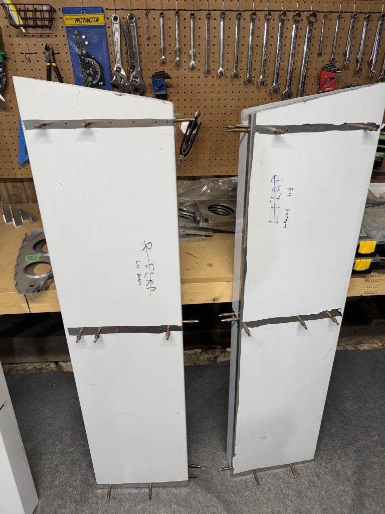
    The kit came with two flaps and two ailerons partially built. They were conveniently set up for the larger sport ailerons, which I wanted to build as they add a fair bit of roll rate. The flaps are mostly done, probably because they are rather simple, though the edges will need to be dressed and there are a few misaligned holes that I will have to massage into place. I also found some spare flap ribs, probably because the kit was purchased to build the normal ailerons. The flaps should be a rather straightforward inspection, finishing, and riveting job.

    I did a very thorough and careful inspection, of course, and noticed that the left hand and right hand flaps were mis-labelled. There are so many glowing errors made in this assembly it’s kind of incredible.

    After taking them apart, I will have to replace all of the flap ribs, as several of the rivet holes are too close to the edge. Oh well.

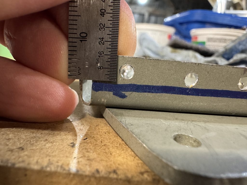
    The rule is the center of the hole has to be at least 2 diameters away from the edge, or a 1/8″ rivet (the most common) has to be 1/4″ from the edge. Sonex does not give the builder a lot of margin here as most rivets are 1/4″ from the edge. At the same time, drawing straight lines is pretty easy.

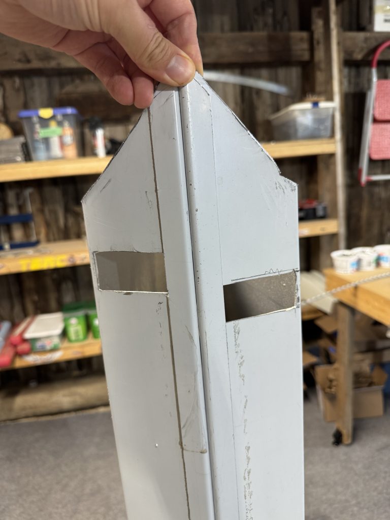
    The ailerons are another story. They are built similar to the flaps, except the drive rib is doubled up and there is a counterweight on the outer end, plus a tip rib with some difficult angles. One of the skins had been cut rather well, but the other had its counterweight hole cut almost an inch inboard of where it should be. Another incredibly obvious blunder.

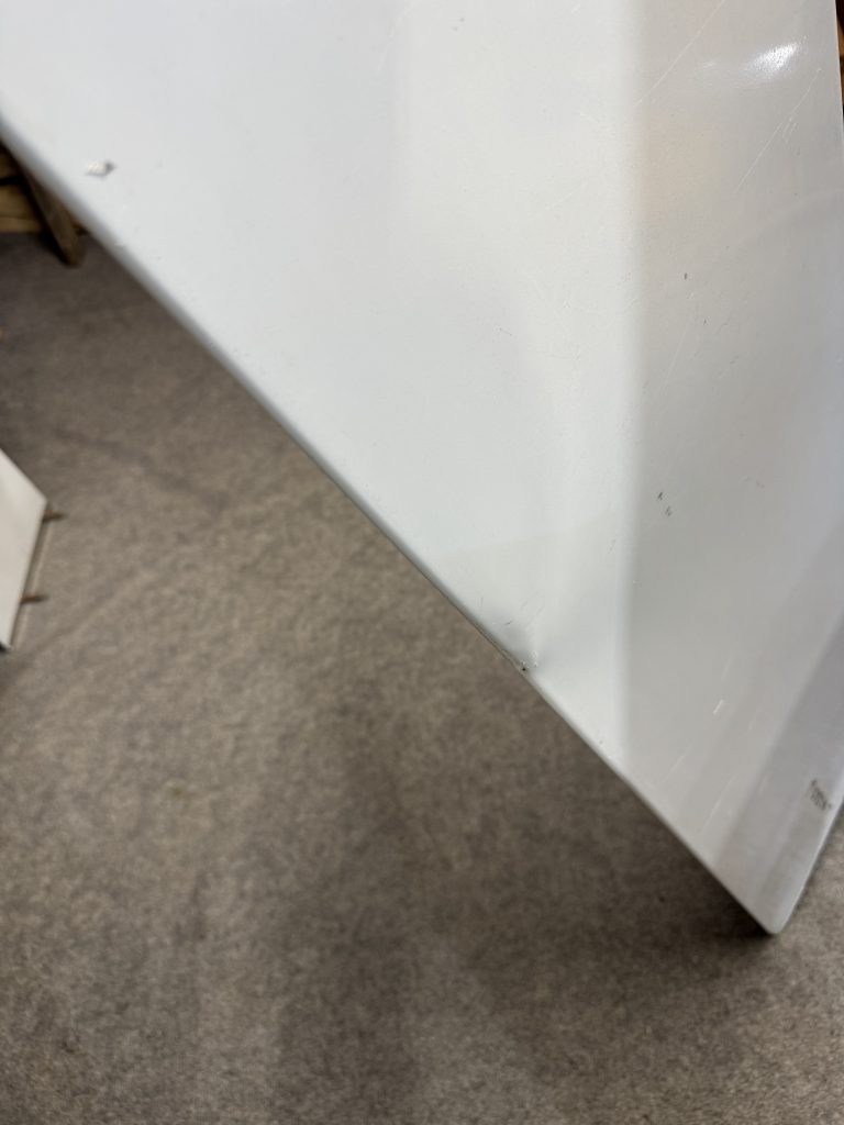
    While thinking of ways I could save it, I dropped it on concrete and ruined the trailing edge. The decision of whether to repair or replace was made for me. I will buy another one from Sonex. This is a $200 USD part.

    One of the aileron drive horns was assembled completely crooked. I took it apart and the drive plate can be saved, so I will only have to buy or make the ribs.

    The other aileron drive was straight but the drive horn was slightly off, about 5/64″ at the attachment. I will ask Sonex if I can keep it, after Oshkosh. I’m pretty sure I can as long as I build both drive horns the same.

    Both of the counterbalance mounts were put together incorrectly; the connecting clips were assembled in what seems to be a random fashion, and they do not clear the aileron skins. I should be able to save these simply by redoing the clips.

    I was wrong again. The mount plates are supposed to be flush to the skin of the aileron and they are spaced well off. All of the ribs will have to be replaced. Since the drill holes on the mounts are also poorly drilled, I will just replace everything.


    So I need parts for the ailerons and flaps, and several parts for the wings. I also need a couple of rivets for the elevators though they are mostly complete. The rudder, horizontal stabilizer, and vertical stabilizer are ready for the pre-cover inspection. That means I will be focusing my energy on the fuselage for the next little while.

  • Rudder ready to rivet

    With the arrival of a whole whack of 3/32″ clecos I could finish the rudder, and move on to finishing other parts of the tail.

    The parcel from ATS is both taped and stapled. Skookum! These guys are serious.
    The last two holes here were tricky to drill as the bit was not long enough, so I broke out the new 12″ aircraft extension drill. What a breeze!
    To drill the hinge I used Jeff Shultz’s idea of drilling into a $3 aluminum ruler to get the correct spacing and offset. It worked great! I put down a second hinge so the ruler would rest flat.
    But, I only drilled 39 holes in the ruler, so had to shift the ruler down one hole and cleco it to get the last hole.
    To get the hinge the correct distance from the surface of the rudder, I clamped a straightedge to the clecos and measured down perpendicular to the edge.
    To ensure the hinge was straight, I drilled with the other half of the hinge attached, and flopped it around from time to time to ensure it didn’t bind up.
    Up-drilling was very fast – now that I have sufficient clecos.
    Taken apart again for deburring and final prep.

    I went to home depot to get some self-etching primer before riveting the rudder, but it was closed due to flooding. It didn’t even rain that much! I will finish the rudder later.


    Next, the trim tab.

    I made the trim tab in just one night and forgot to take many pictures. It went pretty fast: cut a patch out of a large metal sheet, mark the dimensions on the patch, cut out the profile with snips, perform nice final cuts, mark bends then make the bends, cut and drill the hinge (this hinge also required trimming), drill, updrill, deburr, and rivet, mate the part to the elevator, drill, updrill, deburr, rivet.

    I am not very happy with this part. The edges are not very straight which is just cosmetic but still unsatisfying. The arrival of my vixen file should help in the future. The hinge was too close to the trailing edge of the elevator despite adding a small gap to keep it off, so the hinge binds slightly. Also, the hinge on the elevator side is not perfectly flush with the lower surface of the elevator. It will work, but I will wait until the trim system is installed to see if the binding will be a problem.


    The wing spar parts that seemed sketchy will be trashed. Out of 3 main webs none are usable, and one of the doublers will be tossed. The rest is good but I will be placing an order at Sonex sometime after Oshkosh. There are also some wing ribs that were trash and I’ll replace them at the same time. I am not sure if I should order extra parts that I will need some time in the distant future just yet – like the jabiru baffle kit. I think I’ll wait and see. Maybe the exchange rate will get better.

  • First look at the wings

    While waiting for clecos to arrive I had a look at the wings, starting with the spars. The spar is made up of a .125″ center web with .032″ sheet on either side. One of the sheets is the main spar which is about 12 feet (3.6 m) long and the other sheet is called the aft web. On one side of the sandwich is a 0.090″ doubler. The spar caps go above and below the sandwich.

    The story from James is the first builder wanted to put flush rivets through the wing skins into the spar caps. This requires countersinking into the spar caps, which removes some material. Sonex didn’t like that and James bought new spar caps, and had to do some disassembly.

    I had 3 main spars, 3 center webs, 2 aft spars, and 2 doublers. I also had some angle hardware including one wing attach block. This had already been drilled to 1/4″ and drilled to fit the spar. However the holes did not line up at all. As I was making up a bunch of angle hardware anyway, I decided to redo it. I also had to make my first order from Spruce for metal and bolts.

    Not very straight 🙁

    Because there were more components than necessary and some had already been dimpled I had to figure out how to get usable assemblies. Because disassembly had been done there may also have been some destroyed parts.

    Laying out the wing components. I will need a longer workbench!

    I think I will be able to salvage this assembly without buying anything, but I am waiting on Sonex for an opinion.

    The wing ribs looked mostly OK, except for one outer forward rib that was cut into. There were also some mis-rivets on the root rib and some missing parts. Last, the root rib attach angles were not trimmed up and down. I could do this later during a dry fit, to butt up nicely against the spar caps.

    Oops!

    Needing more clecos, I made an order from Aircraft Tool Supply who are very well set-up to cater to Canadian customers! I also got some necessary tools like a microstop countersink for WAY less than Spruce sells it for, and some drill bits.


    I stopped by St-Lambert airport and met a guy with a Rotax 912-powered ultralight trike and a Rotax 914-powered Kitfox. St-Lambert airport is a private grass strip with very low rent and a good community of ultralight and amateur-built pilots. It’s a little further than St-Jean-Chrysostome, and isn’t maintained in winter, but seems like a great place to meet people.

  • Problems

    There are some issues with the fuselage.

    Between the cockpit and the tail cone there is a box strung across the frame. On one side there are two bolts and a rivet that go through, from top to bottom: the upper longeron, a splice plate, the top part of the box, and the rear part of the box. This rivet only goes through the top three components and was mushroomed above the lower-most component. It will have to be removed and replaced.

    According to the plans, this rivet is added rather early on in the assembly process; before the turtledeck is added, and much before the tailcone is joined to the cockpit. There is a fair bit of disassembly to do before the rivet can be removed. It’s surprising that such an obvious error was made. As the box is the only component in the fuselage that has to be inspected during the first pre-close inspection, it will have to be done before proceeding with the build.

    Unfortunately it is not the only error. The cockpit side panels are supposed to be outside of the tailcone side panels. The cockpit side panels are inside of the tailcone side panels, so there is a lip that points into the wind. How or why someone could make this error is beyond me. I will have to separate the cockpit from the tailcone at some point.

    This is not such a bad thing. Committing to regressing a little bit in order to ensure a good quality build is a big mental milestone.

    In the cockpit there are also several mis-rivets and many of the rivets were not assembled according to the plans. Here we see the bottom-most rivet has not been set, and it is also too close to the bottom of the component. It will have to be replaced and another rivet added above it. Above that rivet are two more rivets that have been “snowmanned,” or that have been drilled more than once, making a large hole resembling a snowman. Additional rivets will have to be added, as the holding strength of these rivets will not be the same as correctly drilled rivets.

    At the rear, these rivets have not been drilled according to the plans at all. They are not even identical left and right. The left should be OK, but I will have to add at least two to the right. Why wasn’t this built according to the plans? It’s not hard, and the plans are excellent.

    I still don’t regret buying a kit someone else has worked on, but it sure is hard to find all these obvious errors. How many more will I come across? And, will my tolerance of defects change over time? I will have to be very thorough when going over the rest of the work already done, and carefully analyze the effects of every deviation from the plans.


    I will have to build the seat pan, but the kit did not come with any 0.025″ sheet and my local store did not have any. James did give me a full sheet of 0.032″ and recommended building the seat out of that. The difference will be less than 1 pound and it should be a lot more solid.

    A vixen file is a curved tooth cutting instrument that produces a flat edge by removing lots of metal. The large gaps between teeth and single-direction operation works well for soft metals like aluminum. To make nice flat edges on the control surfaces, I wanted one and could not find one anywhere in Canada. Brown tool has them but I was not ready to place an order from them that justified the shipping cost just yet. Luckily someone on eBay located in Maine was selling new-old-stock vixen files made in England at an attractive price.

    I also got these burrs from Amazon for just $56 and they work great; they are solid and not brazed on, they cut straight and fast and the ground shafts are great quality.


    I was about to complete the rudder assembly, but ran out of 3/32″ clecos. This assembly will be paused as I wait for them to arrive. Someone on Amazon was selling a cleco kit at just about $1 each! At Spruce they are $2!

  • Rudder redo

    I changed my mind about the rudder drive plate and decided to fix it after the new angle meter from Aliexpress arrived. The angle should be 5.2°.

    It was a little hard to get a good measurement with all the components in the way I drilled out all the rivets by hitting them with the #30 until I could break off the tip, then punching out the remainder. My punch needed a little clean up to go in nicely.

    The horn was bent to its correct angle by giving it some love taps with the hammer, checking, and whacking it again.

    A much better fit!

    Below shows the importance of measuring 6 times using 4 different methods and cutting once. I measured x/64ths when I should have measured x/32nds and was quite a bit off.

    To keep the control surface square I wanted to put a cleco in the far end, but making sense of the drawings took a little while.

    In the first photo the rivet going through the hinge is 3/8″ from the top, but measured perpendicular to the end of the short edge. In the second the hinge is spaced 0.057″ from the top surface. It turned out to be much easier to draw and drill once I took the measurements from the correct datum.

    I will redo some of the angles on the control horn; one because my initial drills are now off, and another because it was not correctly aligned.

    On the left you can see the new drill would “snowman” with the other, and on the right one of the rivets would be too close to the edge of the clip.

    Here’s the layout of the larger angle.

    I got these 3/8″ drills from Amazon which came labelled 4.8 mm, but they are actually 3/8″! As the Chinese say, 以实物为准.

    I will drill out the corners with this bit then use the step drill to up-size to a 1/4″ hole. I will also need a seamer, and to modify it a bit. I ground a chamfer into one edge of the seamer so it would bend 1/16″ radius corners nicely.

    The new angle is much smaller than the old one, but it matches the measurements in the plans. It’s so much smaller that it drops into the old angle.

    The front angle required a bit of adjustment as it was also oversize. Finally, the whole assembly fits the control surface much more tightly, and it also more closely matches the other rudder ribs. The last bit of angle was easy to make and trim. The kit came with a ton of angle stock – 16 feet.

    I’m glad I committed to redoing this part.