There are some issues with the fuselage.
Between the cockpit and the tail cone there is a box strung across the frame. On one side there are two bolts and a rivet that go through, from top to bottom: the upper longeron, a splice plate, the top part of the box, and the rear part of the box. This rivet only goes through the top three components and was mushroomed above the lower-most component. It will have to be removed and replaced.
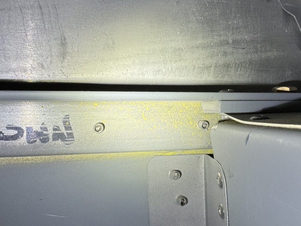
According to the plans, this rivet is added rather early on in the assembly process; before the turtledeck is added, and much before the tailcone is joined to the cockpit. There is a fair bit of disassembly to do before the rivet can be removed. It’s surprising that such an obvious error was made. As the box is the only component in the fuselage that has to be inspected during the first pre-close inspection, it will have to be done before proceeding with the build.
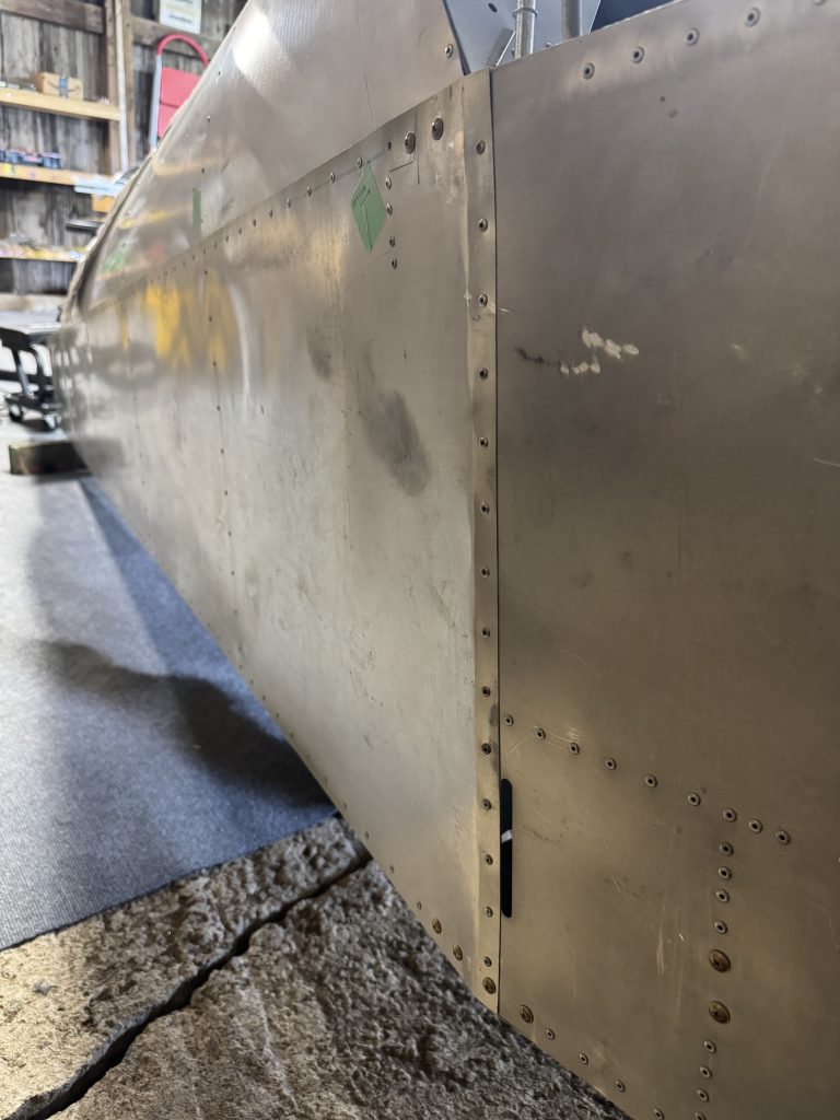
Unfortunately it is not the only error. The cockpit side panels are supposed to be outside of the tailcone side panels. The cockpit side panels are inside of the tailcone side panels, so there is a lip that points into the wind. How or why someone could make this error is beyond me. I will have to separate the cockpit from the tailcone at some point.
This is not such a bad thing. Committing to regressing a little bit in order to ensure a good quality build is a big mental milestone.
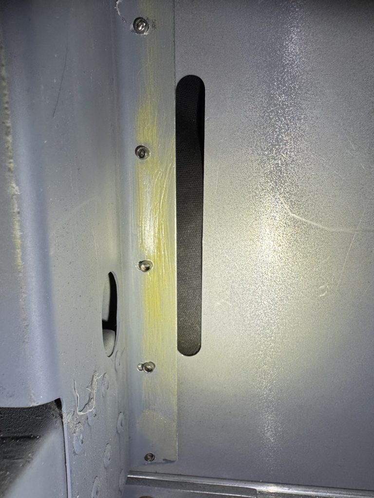
In the cockpit there are also several mis-rivets and many of the rivets were not assembled according to the plans. Here we see the bottom-most rivet has not been set, and it is also too close to the bottom of the component. It will have to be replaced and another rivet added above it. Above that rivet are two more rivets that have been “snowmanned,” or that have been drilled more than once, making a large hole resembling a snowman. Additional rivets will have to be added, as the holding strength of these rivets will not be the same as correctly drilled rivets.
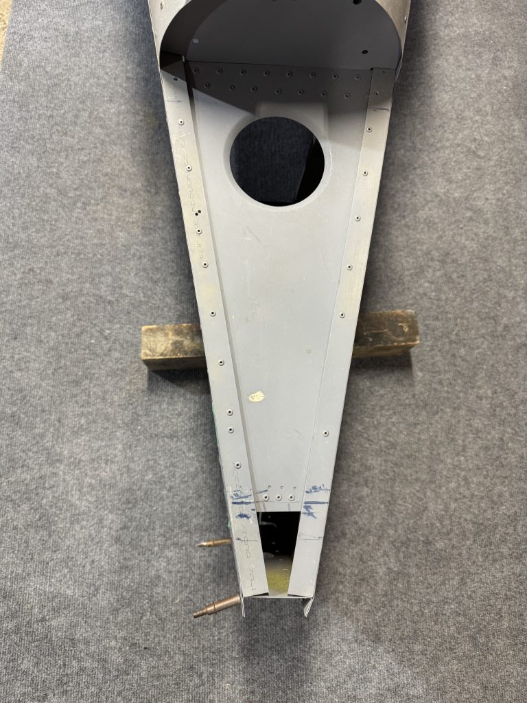
At the rear, these rivets have not been drilled according to the plans at all. They are not even identical left and right. The left should be OK, but I will have to add at least two to the right. Why wasn’t this built according to the plans? It’s not hard, and the plans are excellent.
I still don’t regret buying a kit someone else has worked on, but it sure is hard to find all these obvious errors. How many more will I come across? And, will my tolerance of defects change over time? I will have to be very thorough when going over the rest of the work already done, and carefully analyze the effects of every deviation from the plans.
I will have to build the seat pan, but the kit did not come with any 0.025″ sheet and my local store did not have any. James did give me a full sheet of 0.032″ and recommended building the seat out of that. The difference will be less than 1 pound and it should be a lot more solid.
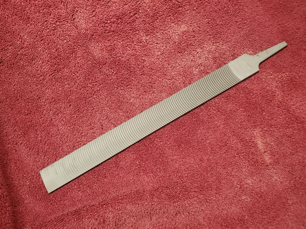
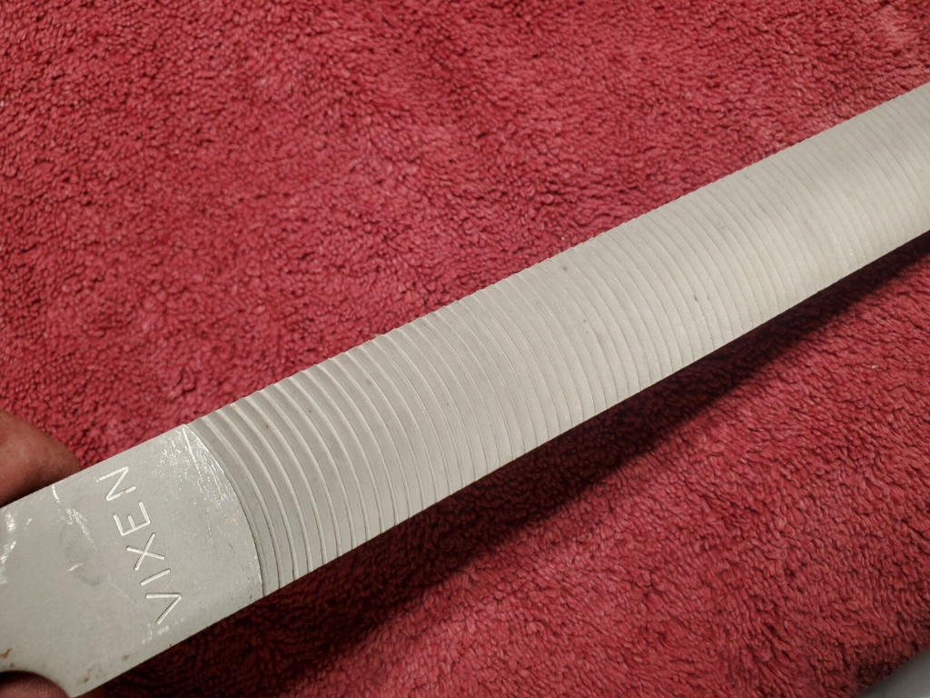
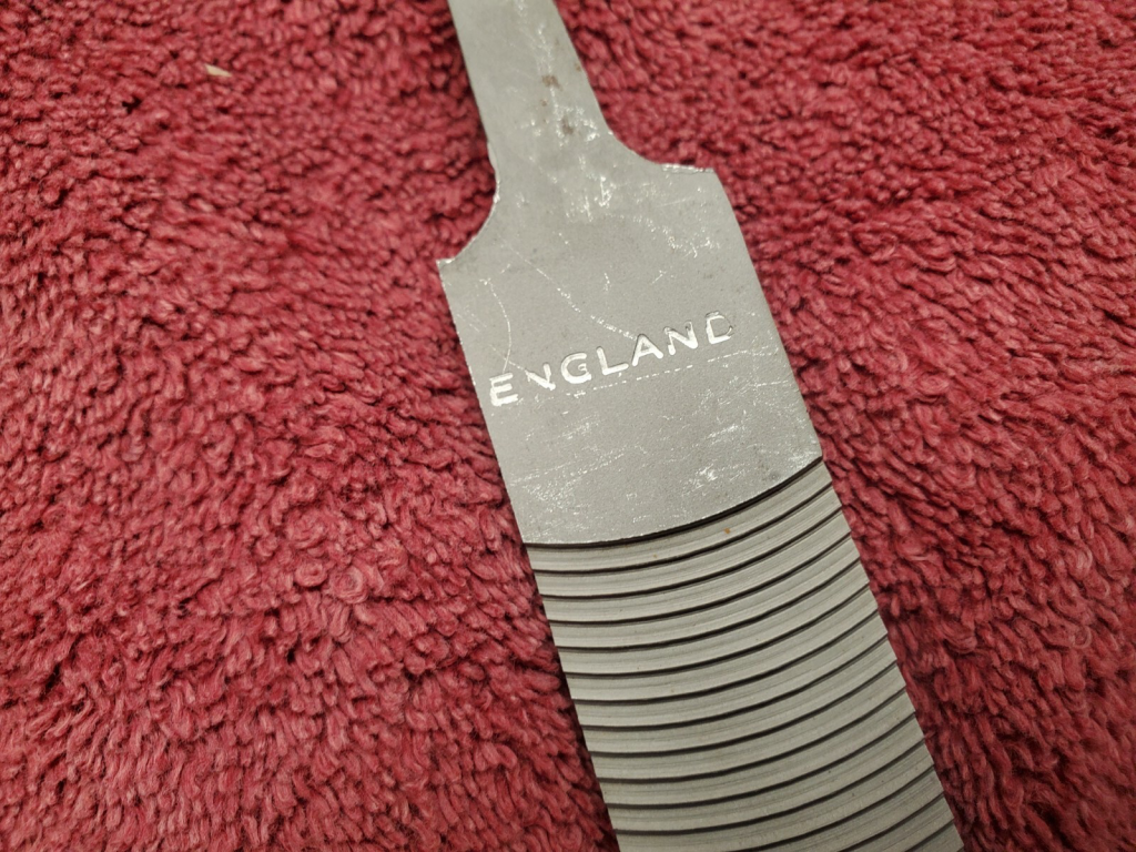
A vixen file is a curved tooth cutting instrument that produces a flat edge by removing lots of metal. The large gaps between teeth and single-direction operation works well for soft metals like aluminum. To make nice flat edges on the control surfaces, I wanted one and could not find one anywhere in Canada. Brown tool has them but I was not ready to place an order from them that justified the shipping cost just yet. Luckily someone on eBay located in Maine was selling new-old-stock vixen files made in England at an attractive price.
I also got these burrs from Amazon for just $56 and they work great; they are solid and not brazed on, they cut straight and fast and the ground shafts are great quality.
I was about to complete the rudder assembly, but ran out of 3/32″ clecos. This assembly will be paused as I wait for them to arrive. Someone on Amazon was selling a cleco kit at just about $1 each! At Spruce they are $2!
