-
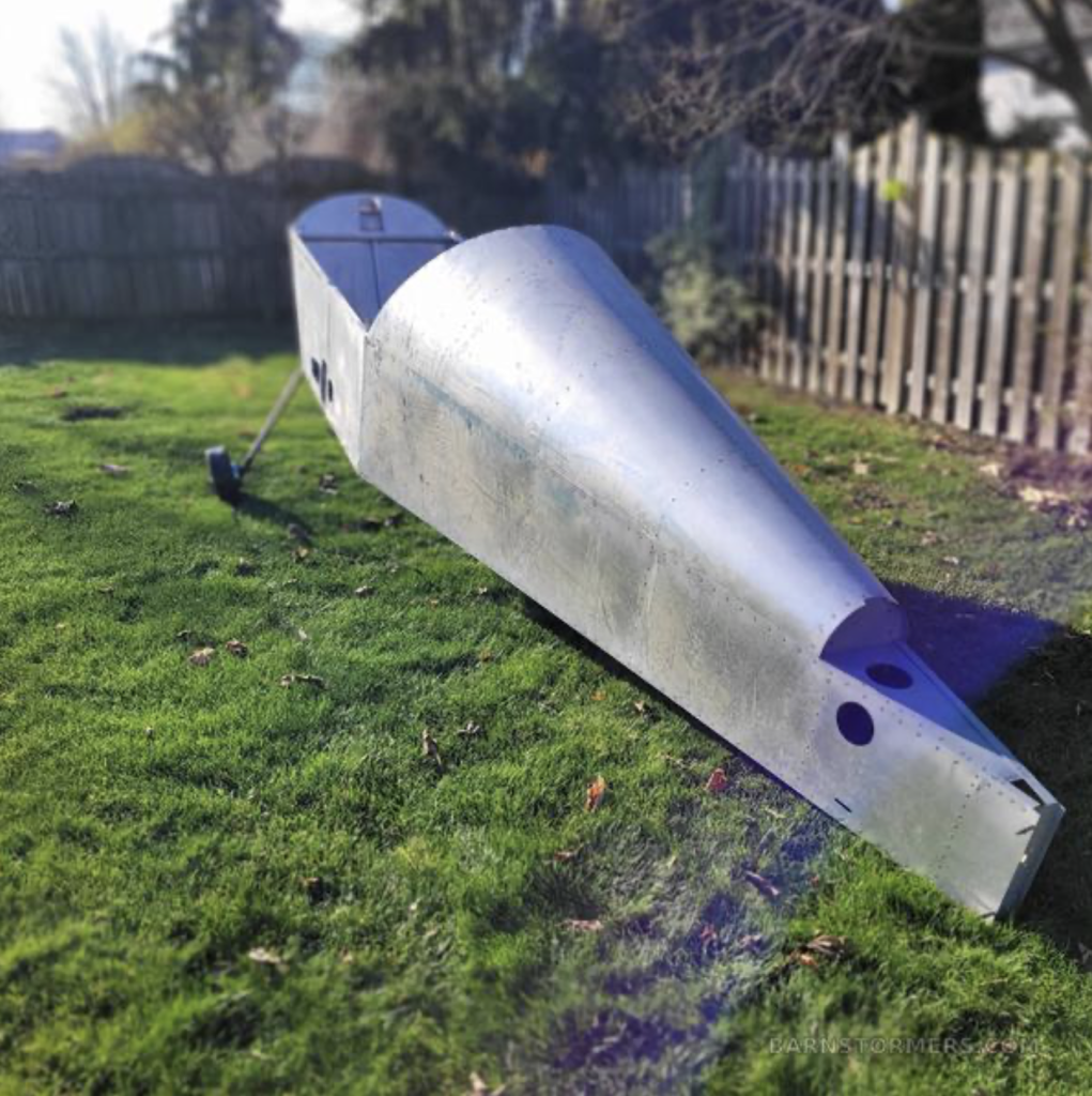
I bought an airplane
Browsing barnstormers, I found the perfect project. For longer than I can remember I wanted to own an airplane. A few years ago I decided I wanted an amateur-built due to lower total operating costs, without the restrictions of the ultra-light class. I wanted a two-seat, aerobatic, simple and convenient weekender. Anything more complex than that I could always rent.
The choices were narrowed down to a Sonex or a Zenith CH650. I had read Jeff Schultz‘ blog and seen videos of the kits, in progress and built.

Sonex 
Zenith A popular, time-tested airframe from an existing company would ensure good support during the build, as I could learn from past experiences building similar aircraft. A kit would save time and probably some cost too. The motors were smaller and from lesser-known companies, but Continental and Lycoming motors are just too expensive. A Van’s would be nice, but prices have skyrocketed and it did not seem to be more cost-effective to build vs. purchasing a certified aircraft.
On Barnstomers, someone was selling an unfinished Sonex kit and Jabiru 3300. I wanted the Jabiru, which is significantly more powerful than the standard VW engine of the Sonex, and allows for a large weight increase. The seller was in Canada, so I would not have to bother with importing anything, and he seemed nice on the phone. With the encouragement of Molie I made an offer without even seeing it. $14,000 beaverbux seemed like a great deal; new Sonex-B kits start at a base price of $50k, without tax, transport, or engine!
I will be picking up Sonex #1279 on the weekend of May 4. Located near Windsor, ON, James Neely bought this kit, also unfinished, with the intention of building his second Sonex. His first Sonex was plans-built and took 11 years to complete. I hope I can finish mine in a little less time.
-
Transportation
The plane being in Essex ON near Windsor means I had to transport it about 1,100 km to get it home. A large enclosure would be required due to the delicate nature of the unassembled components and the long spar caps. I had considered renting a storage container and getting it shipped, as there are transport companies that can ensure the container remains level during loading on the truck, but there were no storage container services that serviced both Quebec and the Essex area. I thought about renting a U-Haul truck but there were none available. The loading height would also be difficult to deal with. U-Haul trailers were too small at 12′.
I found a guy renting trailers locally and he had a 16′ available with a ramp door. Perfect! I booked it for the first weekend in May, way back in February, and decided to tow it with my parents-in-law’s 2019 Mazda CX9. I would need a helper, as the seller, James, is 80 years old, so my dad volunteered to fly in that weekend.
The hitch receiver on the CX9 had never been used, and the rust had to be filed out of it, making this the first metalwork I had to do for the airplane.
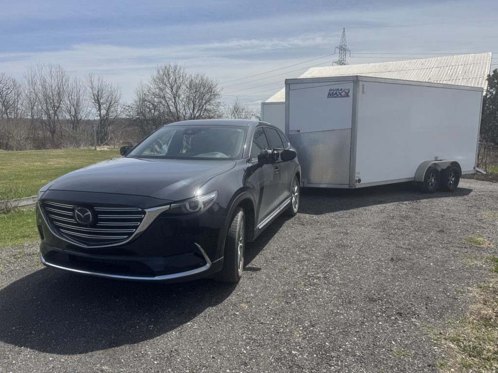
Ready to hit the road! We arrived about 7 am to start loading the plane, which took a little over 2 hours.
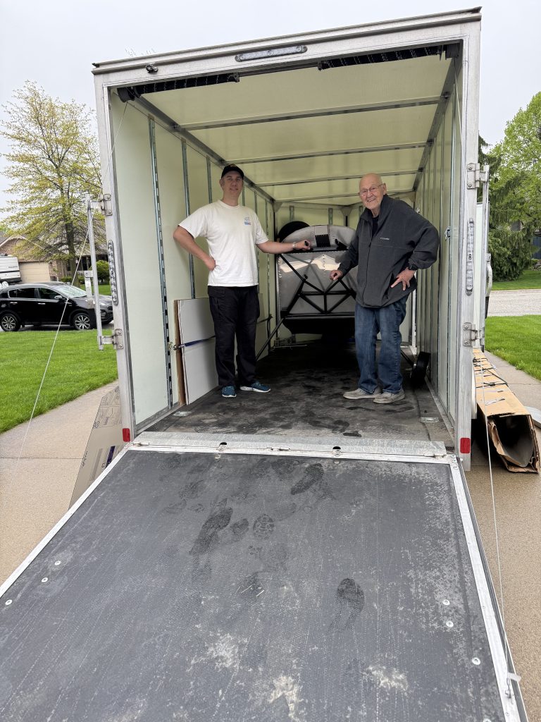
Myself and James with the fuselage loaded. 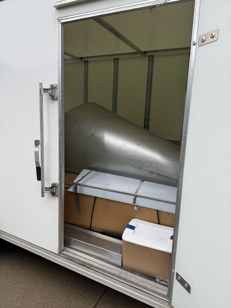
Last check from the side before closing up. 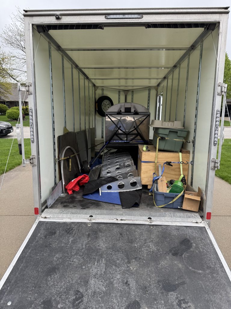
Last check from the back before closing up. We used 480 litres of gas for the trip averaging about 21 L / 100 km at a cost of $645. Plus $460 for the trailer rental (no taxes!) plus $410 for two nights of rentals the bill for transportation was about $1500.
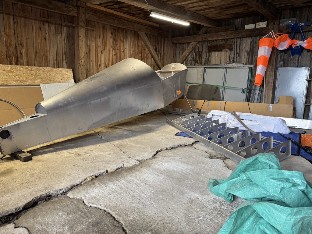
Tucking in at home. Next steps will be to continue cleaning up the shed and building workbenches and tables. I will also start reading the plans. The first steps on the actual airplane will be to inspect the portions already completed.
-
Starting on the workshop
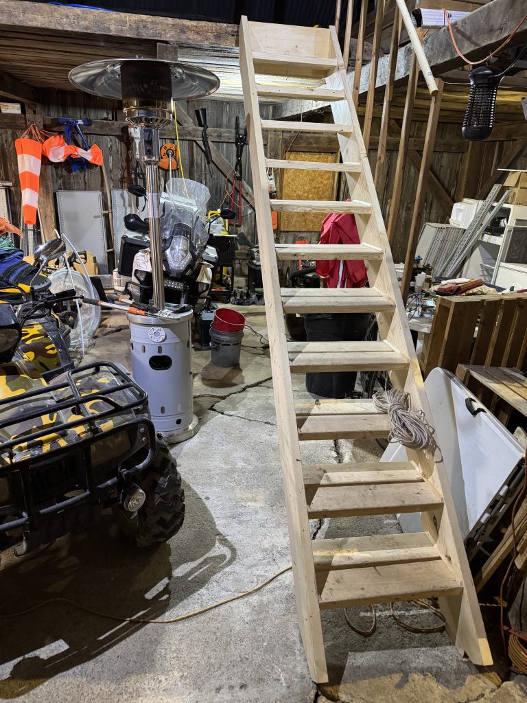
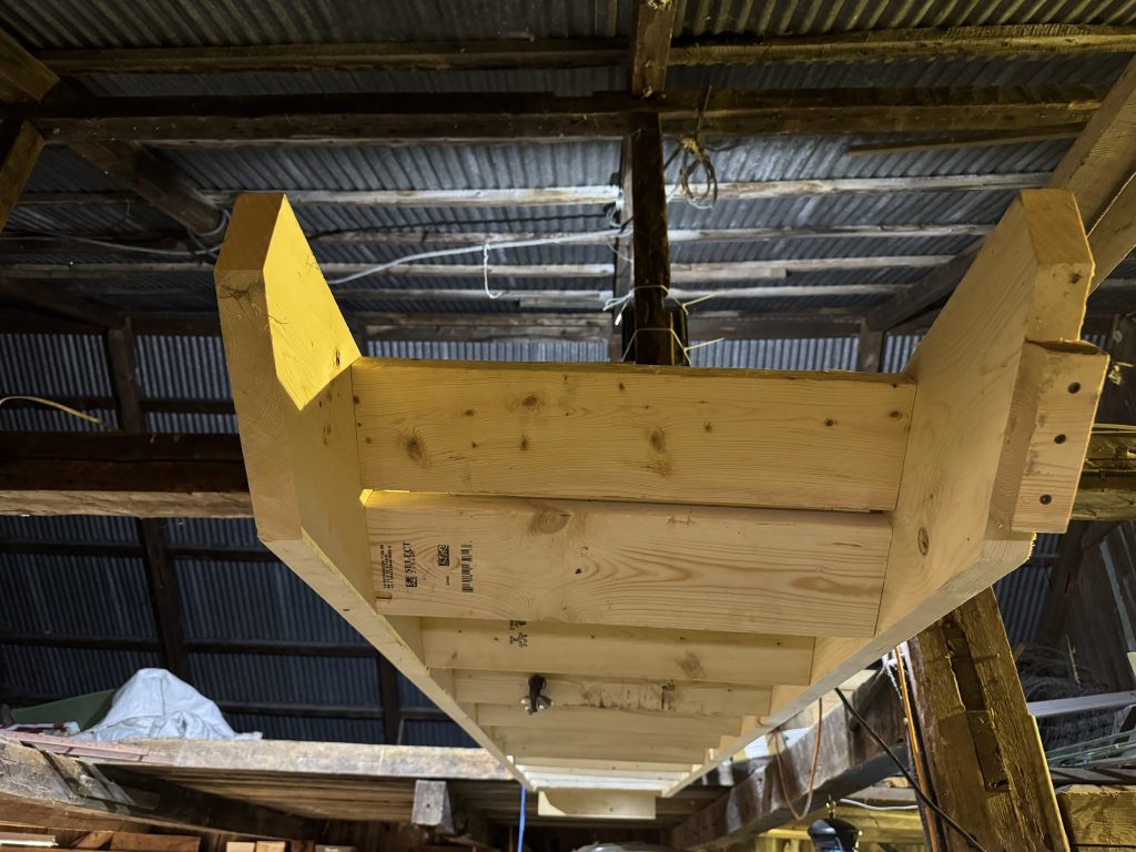
With my dad in town to lend a hand, we started by building a set of stairs to the second level of the garage, which will be used for storage. Previously I only had a rickety metal ladder. We put hinges on the top of the stairs so they could be hoisted out of the way, to move things in and out more conveniently.
It gets very humid here in the warm season and I was worried about the engine in its crate. I soldered a spare SHT4x to an ESP32-C3 with esphome and added it into Home Assistant. Relative humidity was about 50 %. The addition of a small heater dropped that to below 40 % in a few minutes. I will monitor it over the next few days as it dries. I also added temperature control so the temperature in the crate does not get too high.
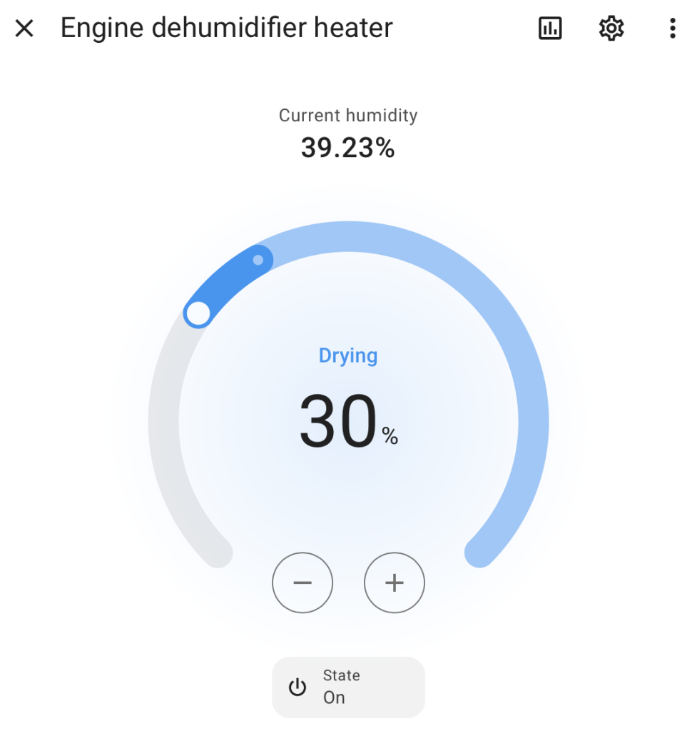
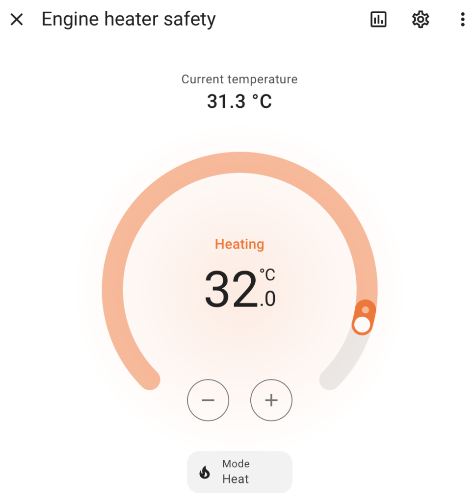
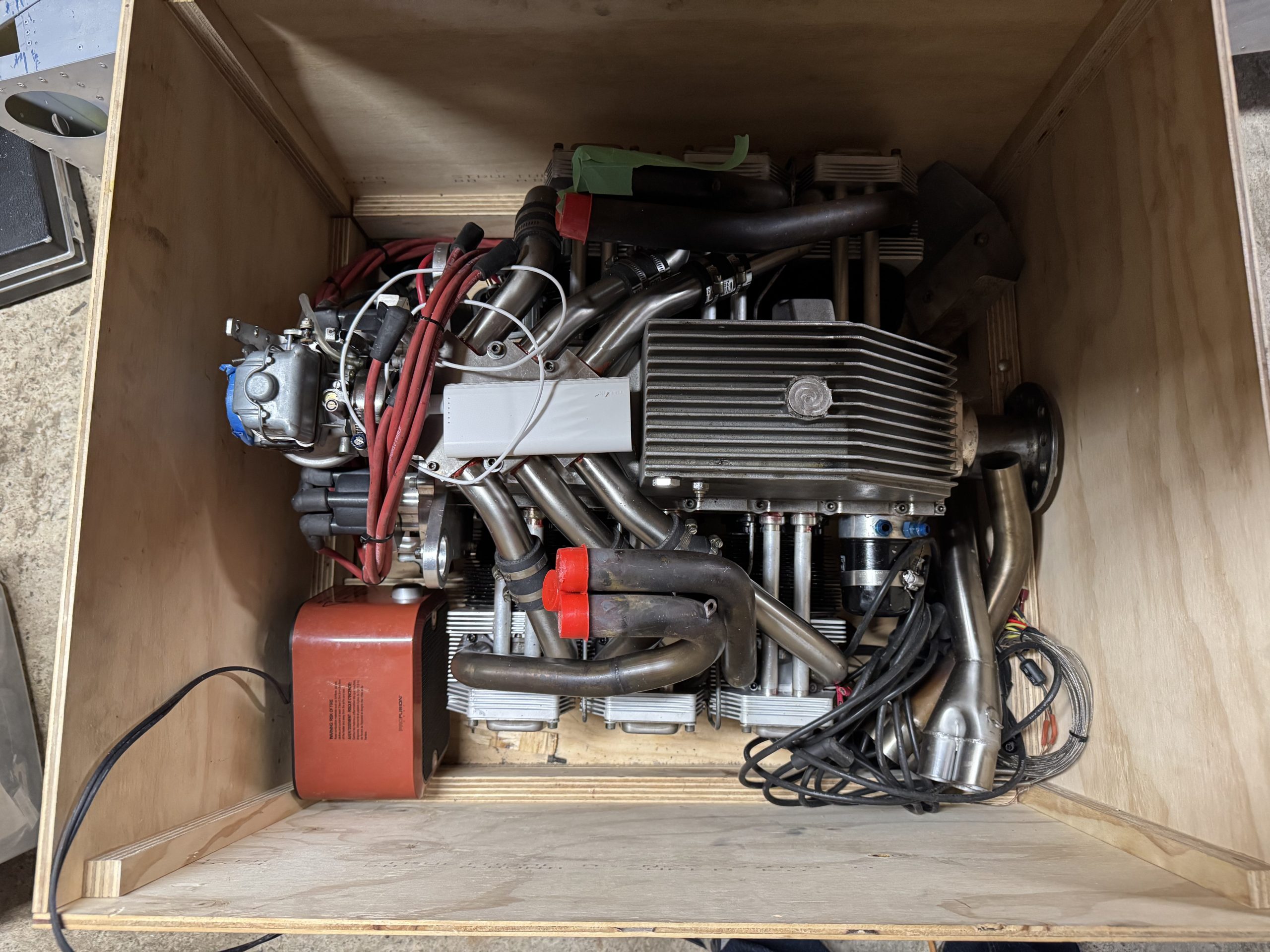
The Jabiru 3300 in its crate with a little heater, and battery bank-powered esphome sensor. Over the next day the humidity dropped to a much more tolerable level, despite heavy rains.
Most of the work so far has been clearing out all the old clutter and dead projects. A newly available storage space about 800 m down the road will allow me to store wood, the abri-tempo, and other stuff I don’t need very often to clear up space for airplane parts. That shed is missing a wall at the moment.
I sent my letter of intent to MD-RA officially starting the build in the eyes of Transport Canada, and paid the first government fee of $125+tax.
Going through the hardware that came with the kit, there seems to be a big mismatch between the hardware I counted and the hardware the plans ask for. There are far too many countersunk driven rivets for example, and I have some bolts that are not in the hardware list at all. There is some hardware missing, including an AN46-7A eye bolt that costs $101.75! Two are needed, good thing I found one.
-
More workshop progress
With the second floor of the garage cleared out, I could start storing parts up there.
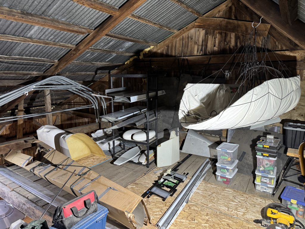
Most of the parts. The canopy is suspended so it doesn’t get scratched. With some space freed up, I can finally see the airplane!
I modelled my half of the garage (Molie gets her half too) in Sweet Home 3D to help me plan it out.
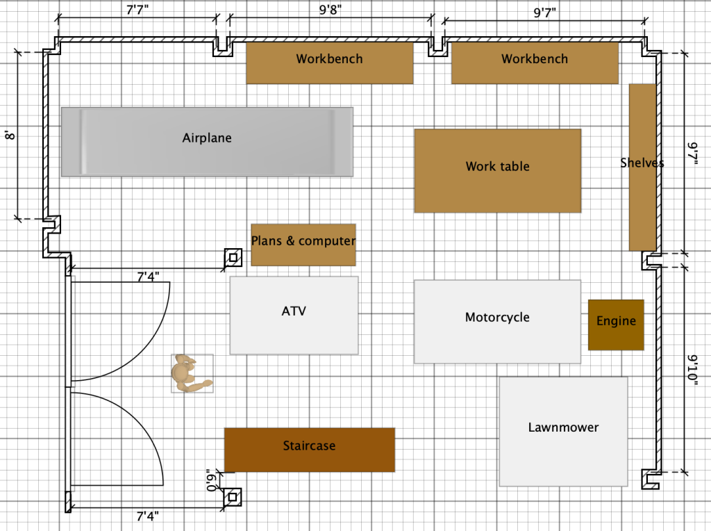
Sonex recommends a 4 x 12′ (1.2 x 3.6 m) work table, but I will try a 4 x 8′ (1.2 x 4.2 m) table for now. The work benches along the walls will hold power tools and pegboard.
The garage is unheated so I picked up this nifty Dantherm VA-M35 military diesel tent heater that is rated at 35 kW, much more power than even the main furnace for the house! It should help keep the work area comfortable even in winter when it hits -25 ℃.
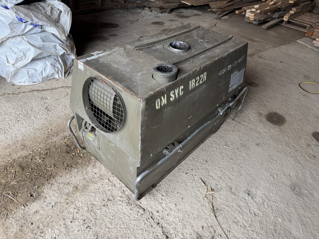
It was just $200! The fan motor was seized however so I removed it and took it to a local electric motor shop. Otherwise it works quite well, and because it was made in Denmark it even has metric hardware.
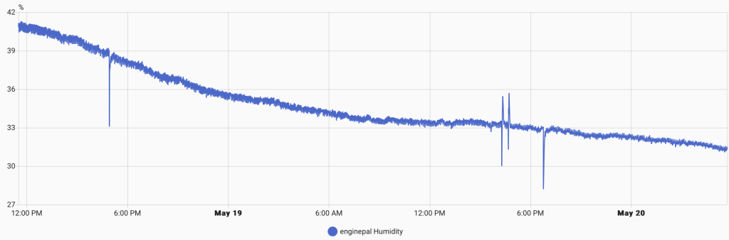
I was unhappy with the “dehumidifier” as the temperature outside increased, so picked up a very cheap peltier dehumidifier. I would not want to use one of these things to dehumidify a room, but it seems to work well for a small box. It has some digital electronics inside and a 5V supply so I should be able to make it controllable with esphome without much effort, but for now it just runs all the time.
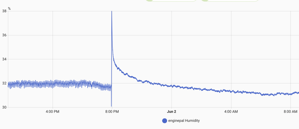
Engine humidity before and after changing to the peltier dehumidifier. 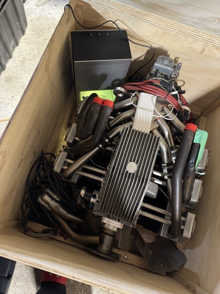
The humidifier next to the engine. Sifting through the paperwork that came with the plane, I found notes from the previous owner James. He had invested 341 hours over about 2 ¼ years before selling it. Quite a bit of time was spent undoing some of the unsatisfactory work done by the first owner.
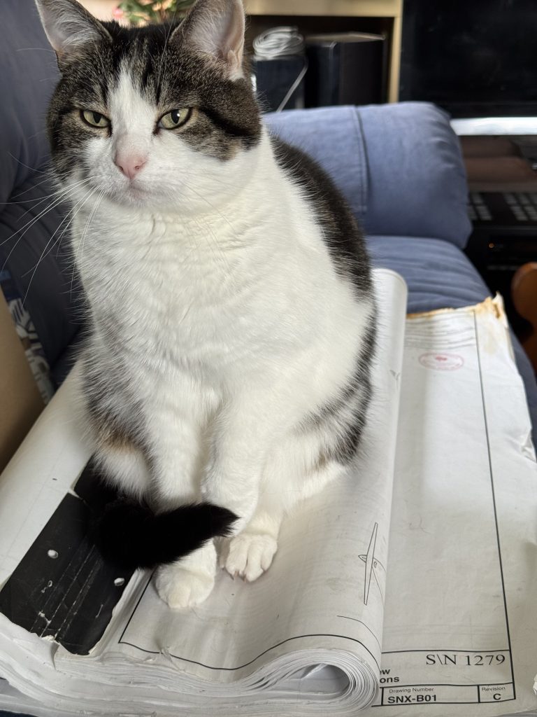
Ending this post with a cat picture. -
Taking stock
Now that I have a place to work, I am beginning to assess the parts of the build already done and prepare for the first major milestone. Canadian rules require an inspection of all areas that will be closed-off for the final inspection, and at the same time for the assembly to be as advanced as possible. This complicates planning as pretty much all the metal parts have to be in a mostly-finished state.
The first builder was in USA which does not have this pre-cover inspection requirement, and consequently the airplane was not built with inspection in mind. The second builder, James, was in Canada and had do undo some of the work of the first builder to prepare for the inspection.
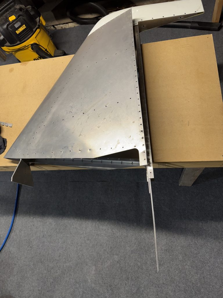
The left surface of the vertical stabilizer had its rivets drilled out so the inside could be inspected. Opening it up reveals a job well done. The skin edges were rather rough and I busted my first knuckle on it, so the plane drew first blood on day 1.
The fibreglass tip had been riveted on. Talking to my local MD-RA delegate Mathieu, they are prohibited from using borescopes to perform inspections as it overly complicates matters if a build fails inspection. The tip will have to come off.
There is a spar web and attach angle that should be on the tail. I found the attach angle in a parts box, and found the web already riveted to the fuselage. The lower attach angle was floating around where it will eventually be attached.
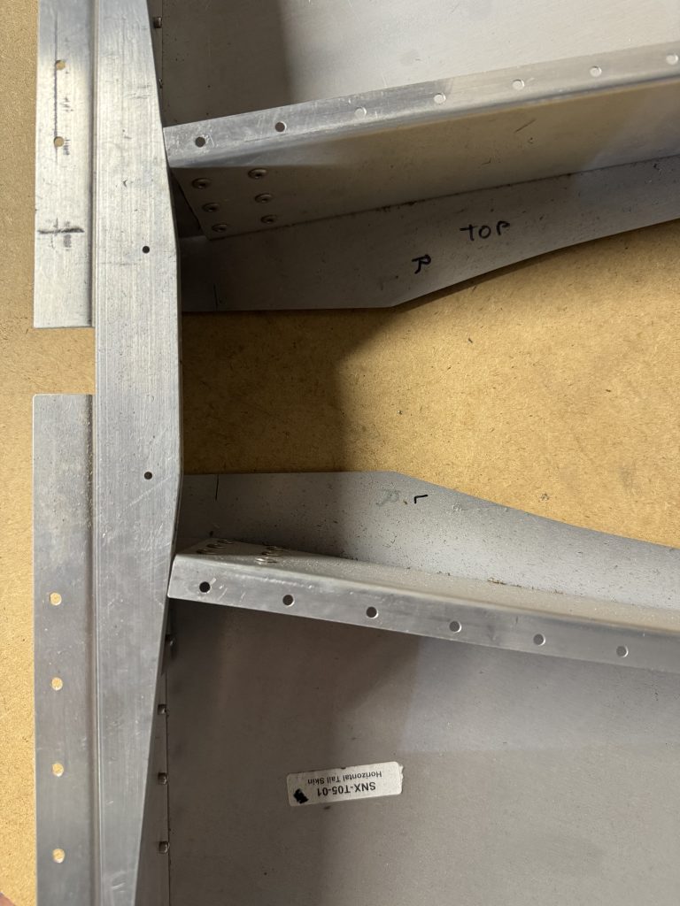
Taking apart the horizontal stabilizer, I also found a nice quality of build. There was just one curiosity: the left and right horizontal stabilizer skins had been mis-labelled by a previous builder, with right and left swapped. They had been correctly installed so I am not sure how this could have happened. I will have to keep an eye out for similar errors.
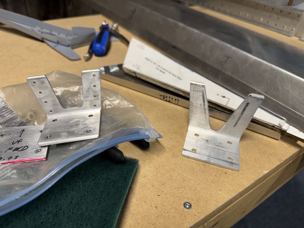
As the horizontal stabilizer tips had been cut to size I test-fit one just for fun. The tips and ribs were correctly labelled left and right. Curiously, I found two complete sets of fibreglass tips and tip ribs in the kit.
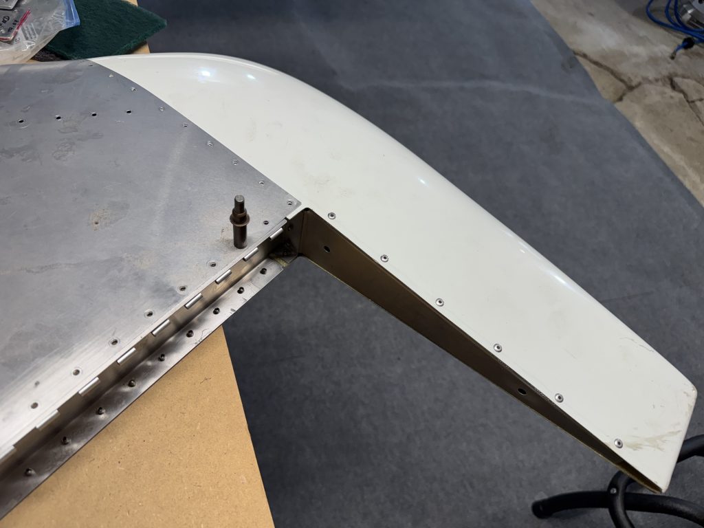
Finally, the trim tab had not been fabricated, and the nutplate had not been attached to the elevator control horn. The trim tab can wait, but the nutplate has to be done before elevator closure.
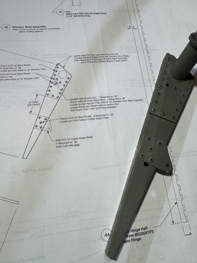
The plans call for an AN366F-832 flush nylock nutplate which Aircraft Spruce doesn’t have; they do have AN366F-832A which is $15.50 at Aircraft Spruce and backordered, and I am not sure what the difference is. The hardware list calls for 4 pieces.
Digging a little deeper, AN366 was superseded by MS21047F and AN366F-832 can be substituted with MS21047-08, which are $1 and stocked (although they only have the variant with dry lube).

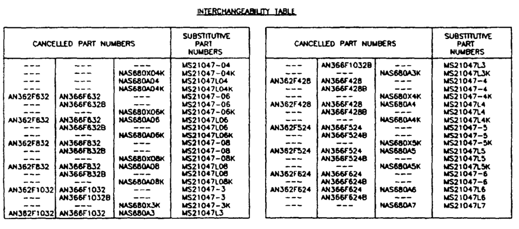
These tables were from a document found on EverySpec, which I had never heard of. What a useful resource!
I also have to wonder why the plans ask for a SSC-34 rivet here, which is a non-stainless steel 3/32″ flush pop rivet.
Searching for SSC-34 on Aircraft Spruce produces no results, but they do have the rivet (Part# 04-02338 “CHERRY RIVET SSC-34”). Maybe their search feature does not like the dash.
Last, the local metal shop does not have 0.025″ sheet aluminum, which I will need for the seat pan. Spruce has this of course, so I will be planning for a big order…
-
First cuts ✂️
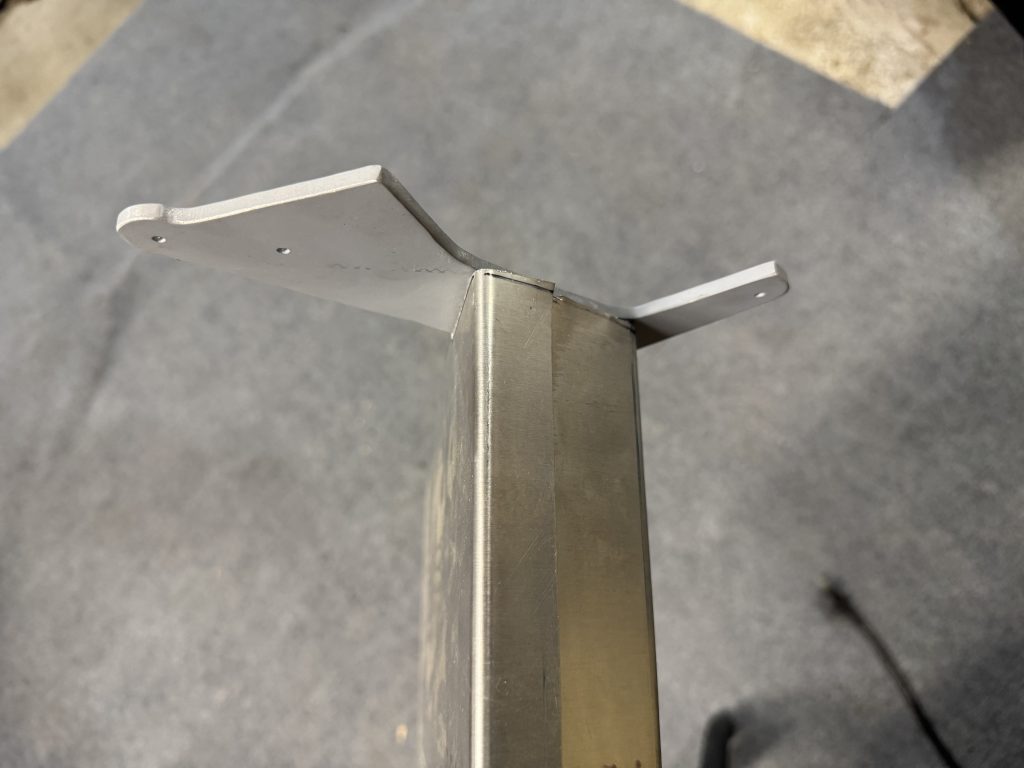
The rudder control horn was already completed, although the 5.2° bend is a little off. Since it is already riveted together and primed I’m just going to use it.
I transferred the end cuts to the control surface stock. Since the stock is a few inches too long, if I mess up I have enough material to try again. Drawing a straight line on a curved surface, then drawing that same line on the opposite surface is a little tricky!
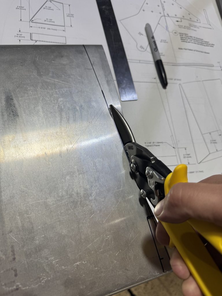
Looks alright I think!
Some of the edges were a little wonky however and I decided to do it again to improve my technique. First, I drew better cut lines using an Ultra-Fine point sharpie.

Then instead of using shears, I made a rough cut on the bandsaw
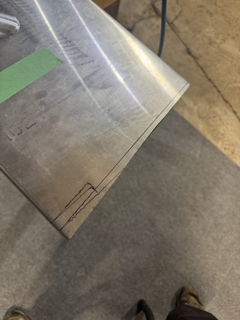
then got in close with the shears, and used a coarse file to finish and make the edge straight. I think next time I will try a burr.
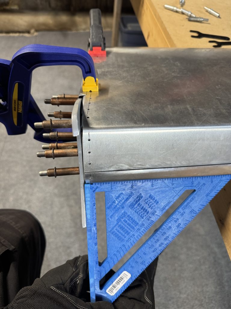
Fitting the control horn straight was a little tricky. I drilled one rivet when it was mostly square, then drilled another after squaring it up.
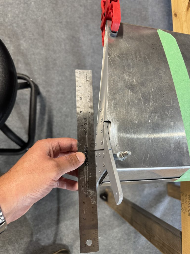
By holding the straightedge and square together at the same time, I could get the horn really straight.
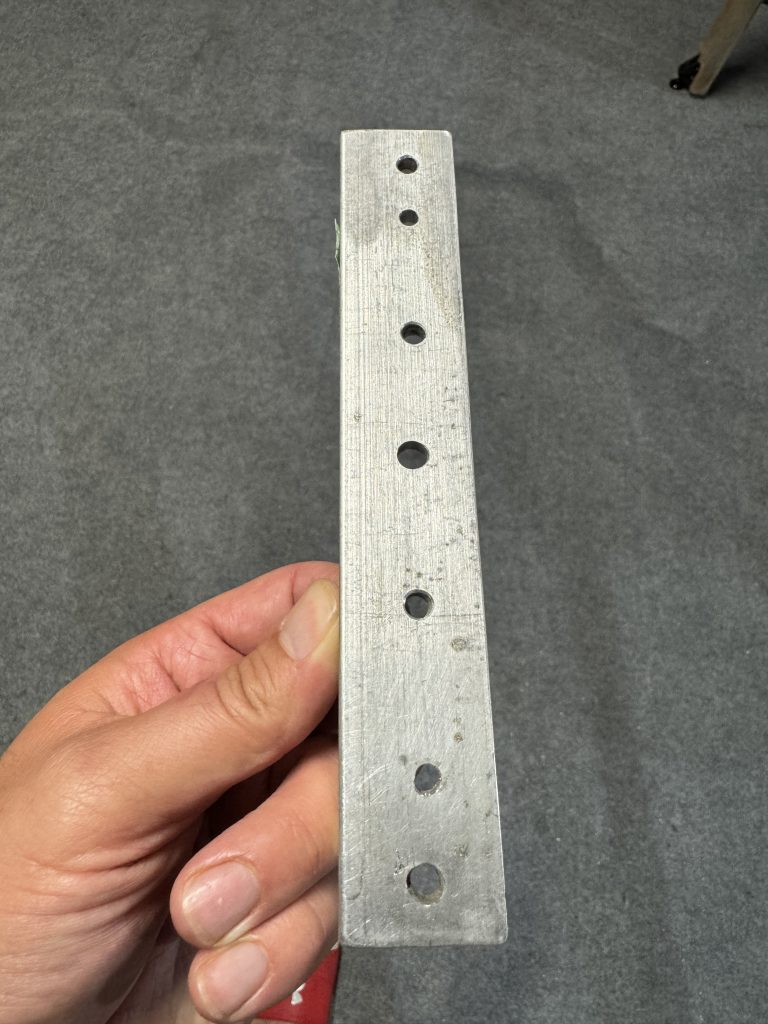
I will have to drill a bunch of rivet lines and hinges. A rivet spacer on Spruce is $90! I’m building an airplane, not a public art installation. With a $3 aluminum ruler from Canac, I drilled holes precisely where they needed to be, and can make a few of them, as Jeff shows on his blog.
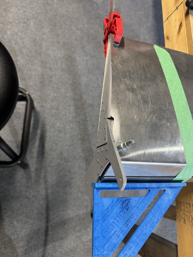
My first line was a little off! Turns out it was the clamp that added a bit of tension. Clamping from the end and not the side solved the problem.
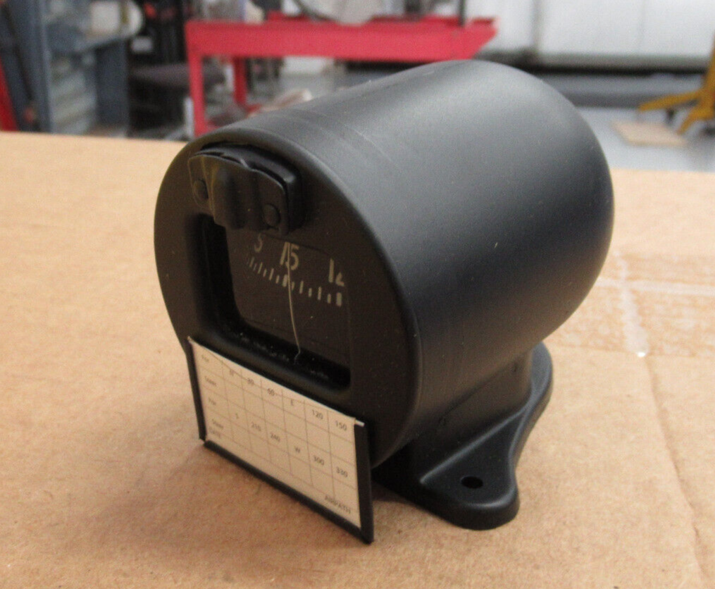
A mechanical compass is a requirement in Canada. An Airpath pedestal compass is over $500, plus tax! Someone was selling an illuminated model on eBay for $250, so I snagged it. Unlike electronic instruments, a compass is very unlikely to be outdated by the time I need it.
-
Rudder redo
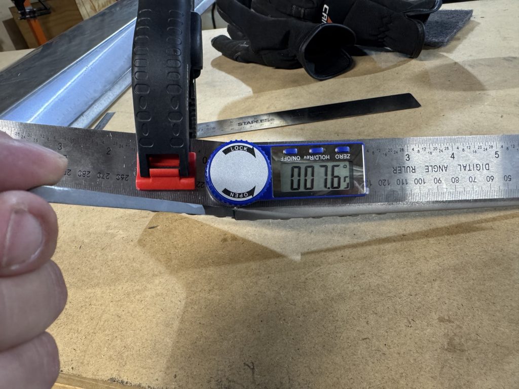
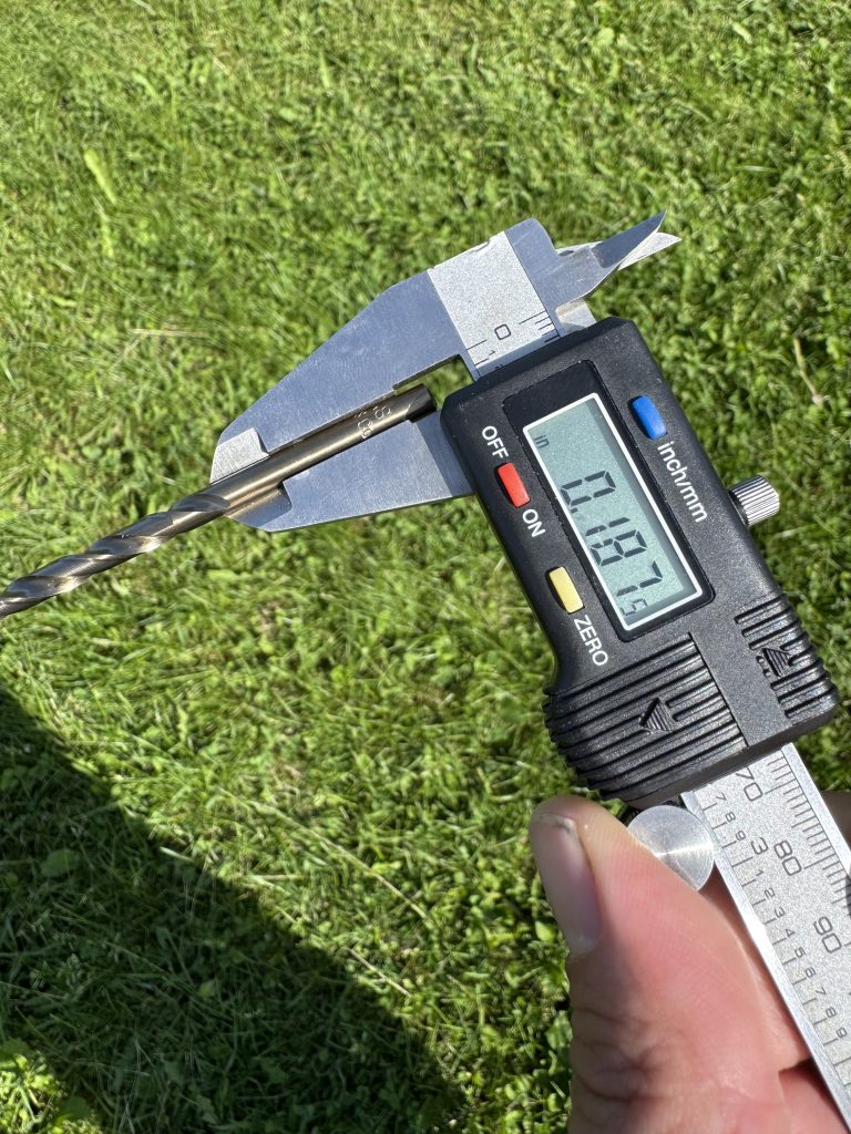
I changed my mind about the rudder drive plate and decided to fix it after the new angle meter from Aliexpress arrived. The angle should be 5.2°.
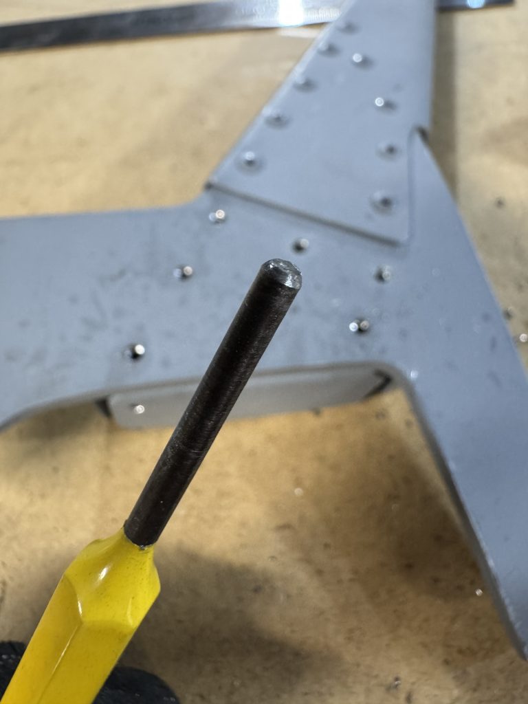
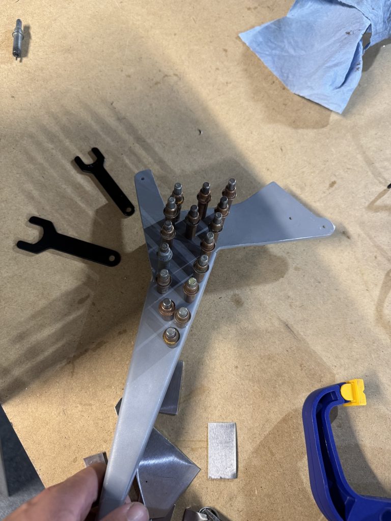
It was a little hard to get a good measurement with all the components in the way I drilled out all the rivets by hitting them with the #30 until I could break off the tip, then punching out the remainder. My punch needed a little clean up to go in nicely.
The horn was bent to its correct angle by giving it some love taps with the hammer, checking, and whacking it again.
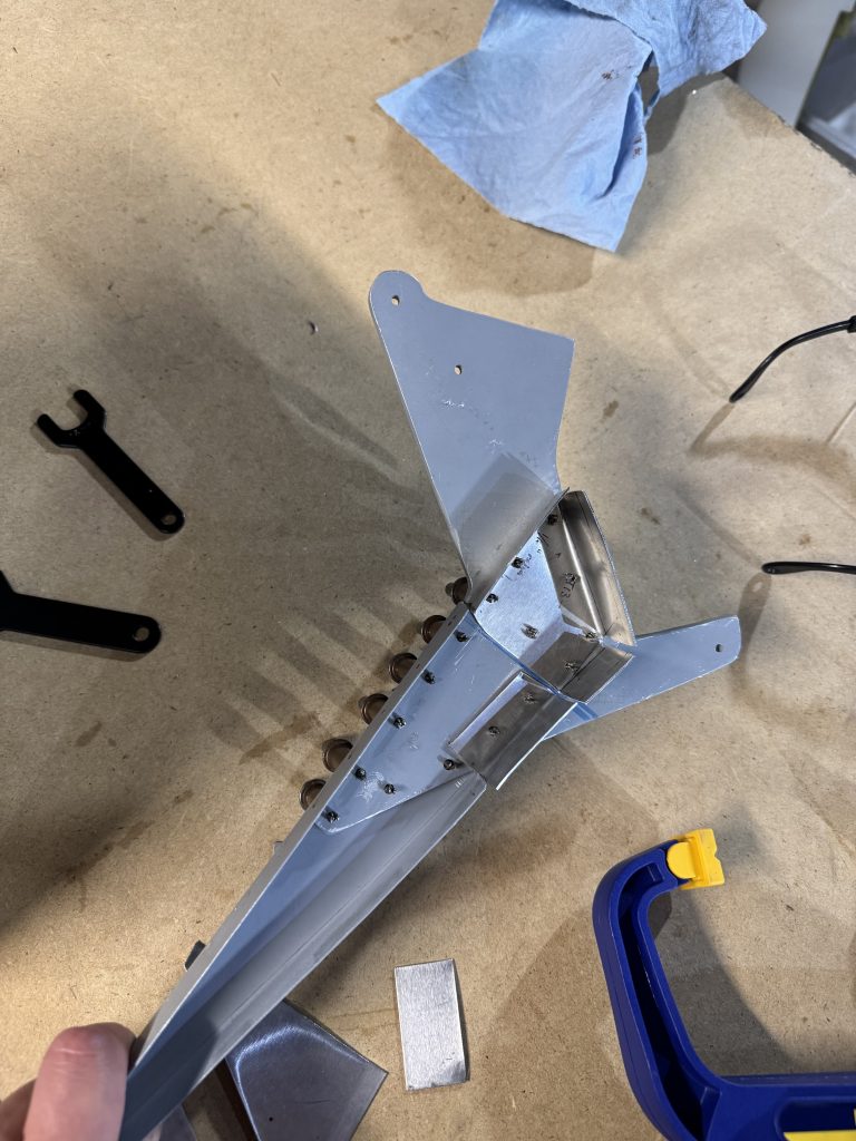
A much better fit!
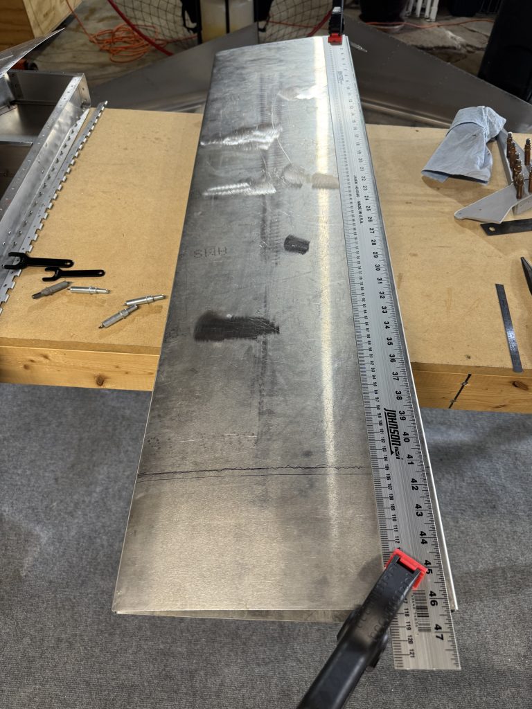
Below shows the importance of measuring 6 times using 4 different methods and cutting once. I measured x/64ths when I should have measured x/32nds and was quite a bit off.
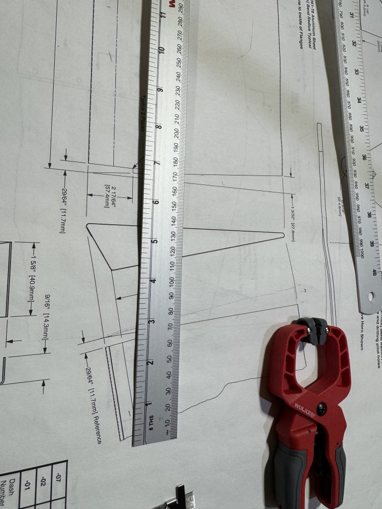
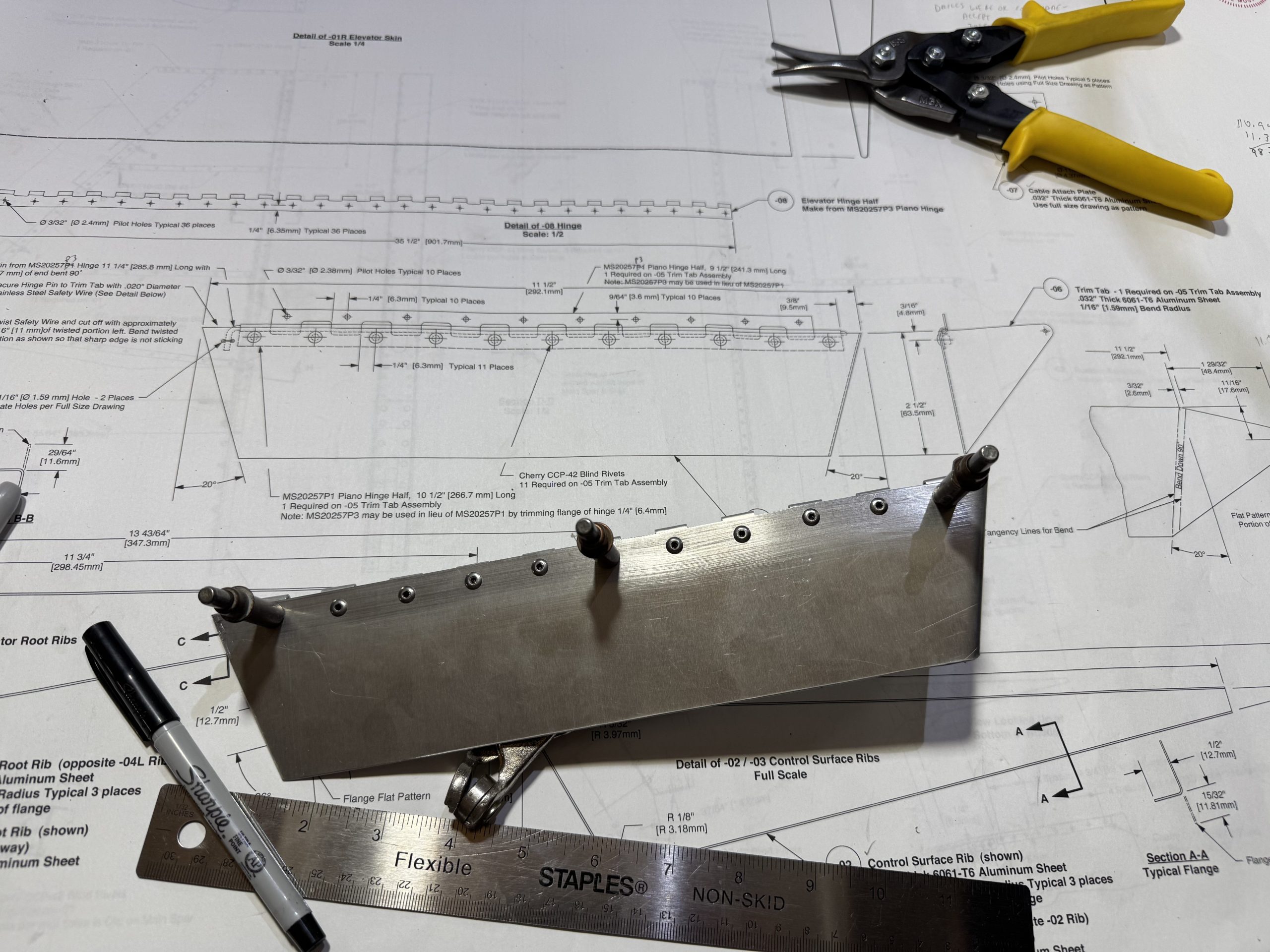
To keep the control surface square I wanted to put a cleco in the far end, but making sense of the drawings took a little while.
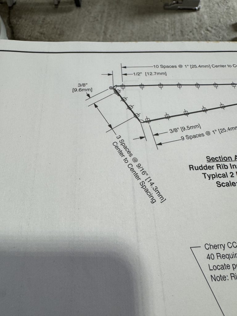
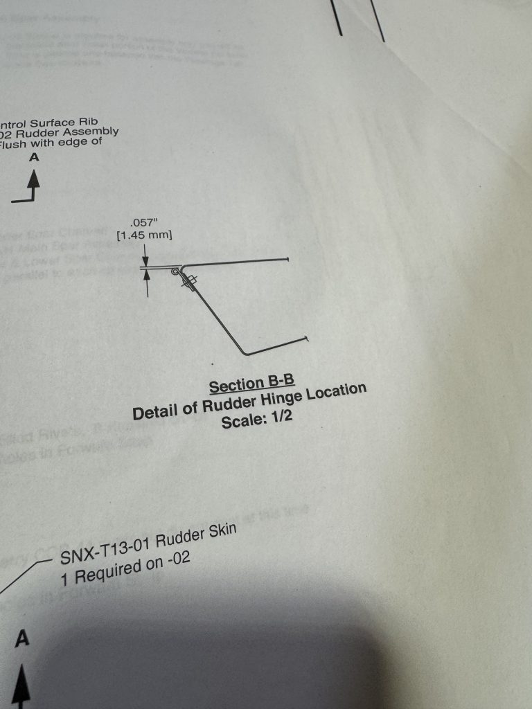
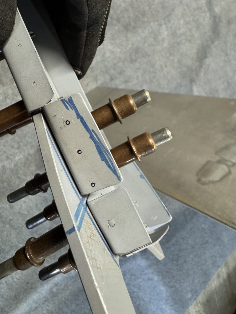
In the first photo the rivet going through the hinge is 3/8″ from the top, but measured perpendicular to the end of the short edge. In the second the hinge is spaced 0.057″ from the top surface. It turned out to be much easier to draw and drill once I took the measurements from the correct datum.
I will redo some of the angles on the control horn; one because my initial drills are now off, and another because it was not correctly aligned.
On the left you can see the new drill would “snowman” with the other, and on the right one of the rivets would be too close to the edge of the clip.
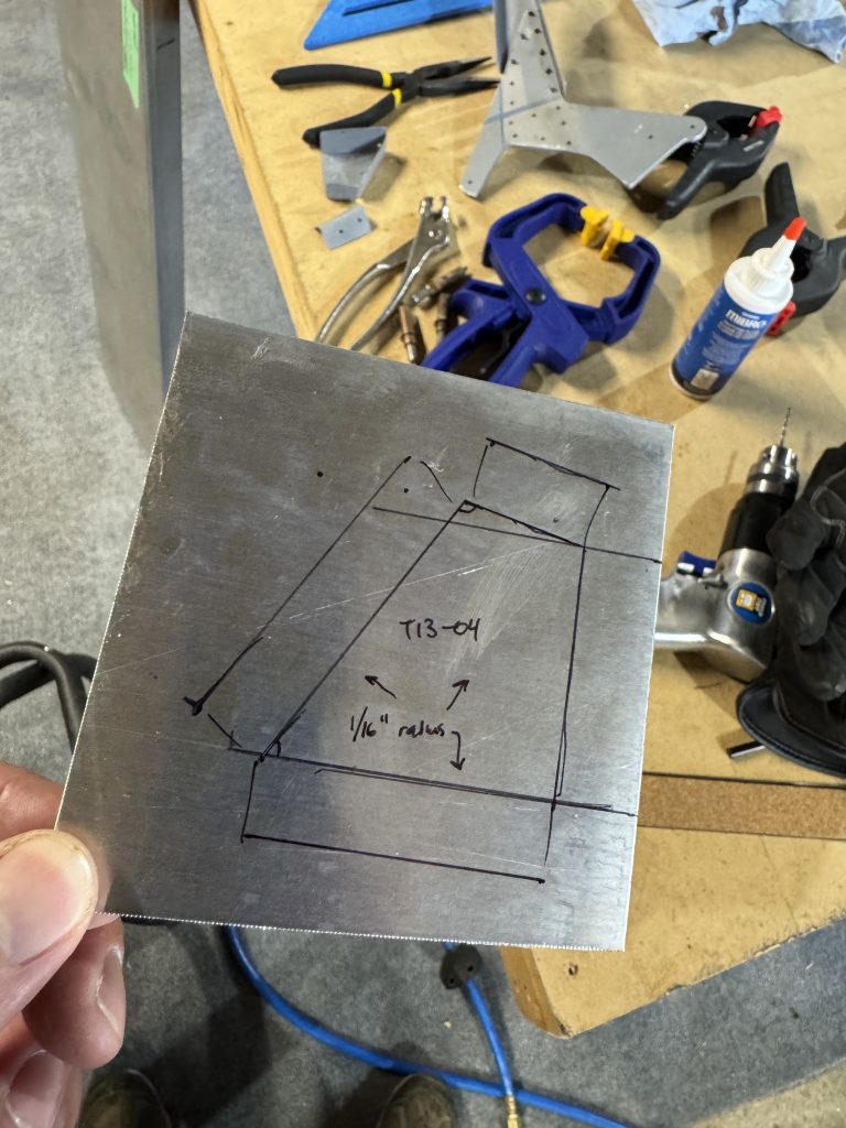
Here’s the layout of the larger angle.
I got these 3/8″ drills from Amazon which came labelled 4.8 mm, but they are actually 3/8″! As the Chinese say, 以实物为准.
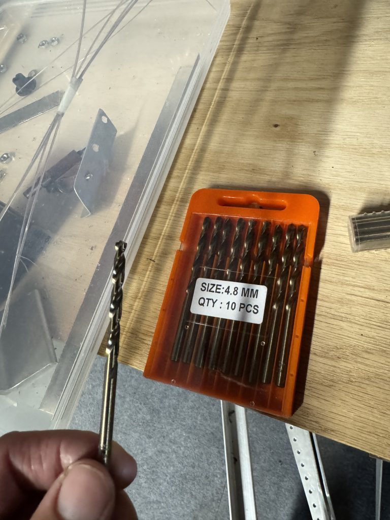
I will drill out the corners with this bit then use the step drill to up-size to a 1/4″ hole. I will also need a seamer, and to modify it a bit. I ground a chamfer into one edge of the seamer so it would bend 1/16″ radius corners nicely.
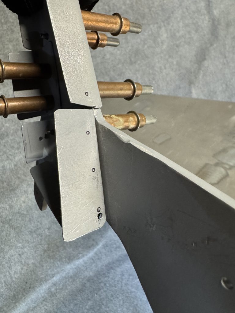
The new angle is much smaller than the old one, but it matches the measurements in the plans. It’s so much smaller that it drops into the old angle.
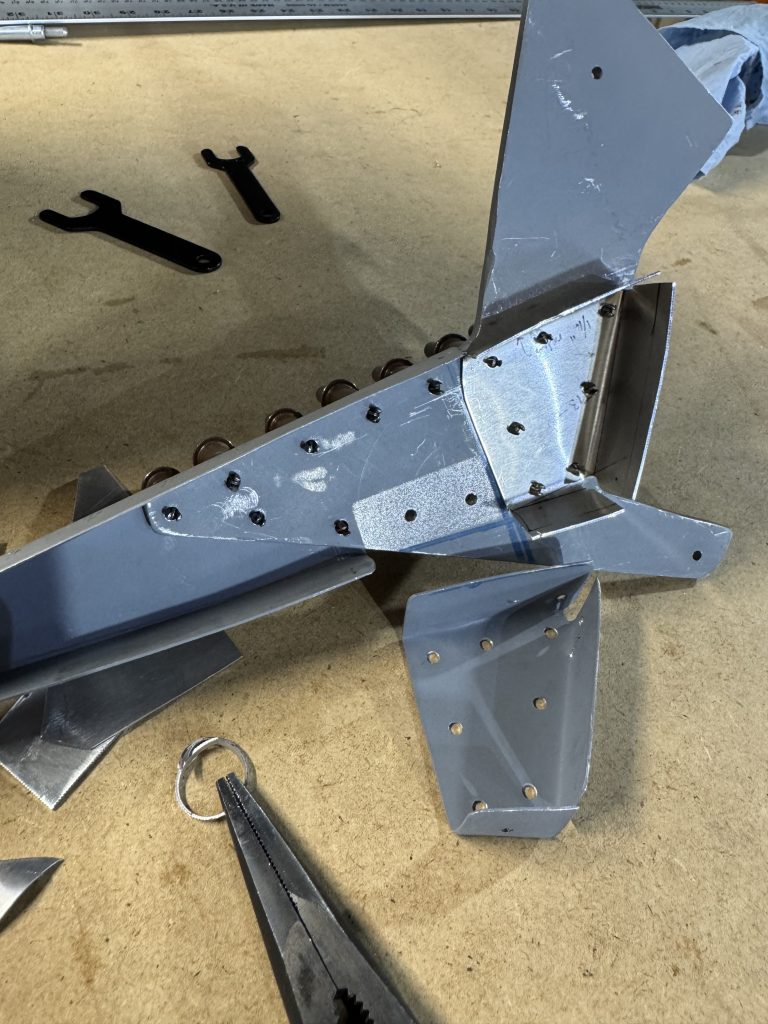
The front angle required a bit of adjustment as it was also oversize. Finally, the whole assembly fits the control surface much more tightly, and it also more closely matches the other rudder ribs. The last bit of angle was easy to make and trim. The kit came with a ton of angle stock – 16 feet.
I’m glad I committed to redoing this part.
-
Problems
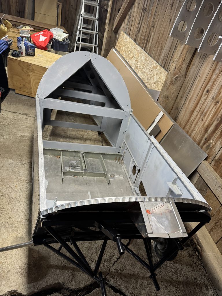
There are some issues with the fuselage.
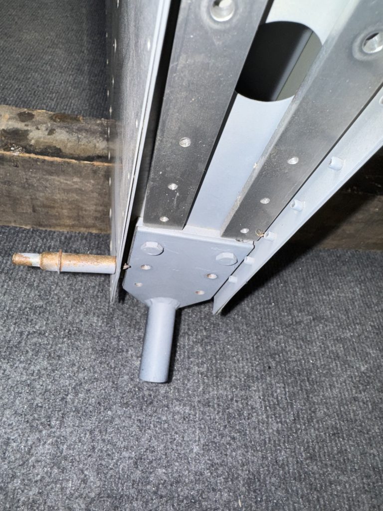
Between the cockpit and the tail cone there is a box strung across the frame. On one side there are two bolts and a rivet that go through, from top to bottom: the upper longeron, a splice plate, the top part of the box, and the rear part of the box. This rivet only goes through the top three components and was mushroomed above the lower-most component. It will have to be removed and replaced.
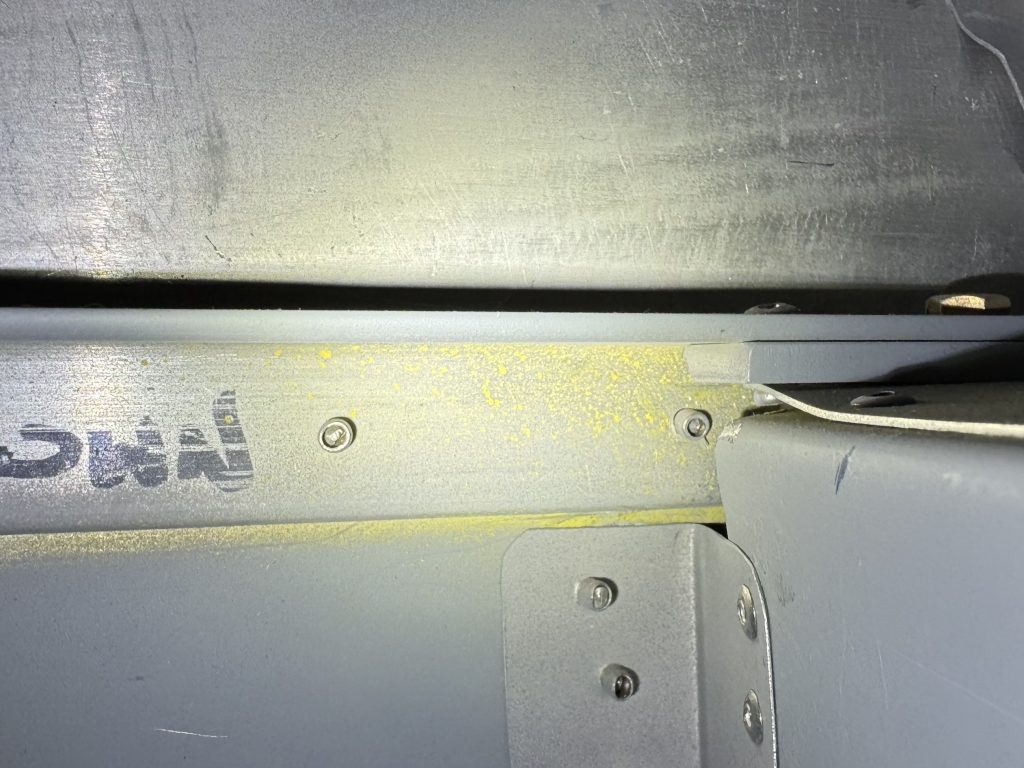
According to the plans, this rivet is added rather early on in the assembly process; before the turtledeck is added, and much before the tailcone is joined to the cockpit. There is a fair bit of disassembly to do before the rivet can be removed. It’s surprising that such an obvious error was made. As the box is the only component in the fuselage that has to be inspected during the first pre-close inspection, it will have to be done before proceeding with the build.
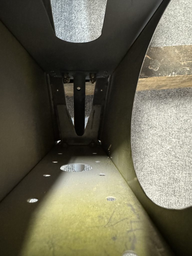
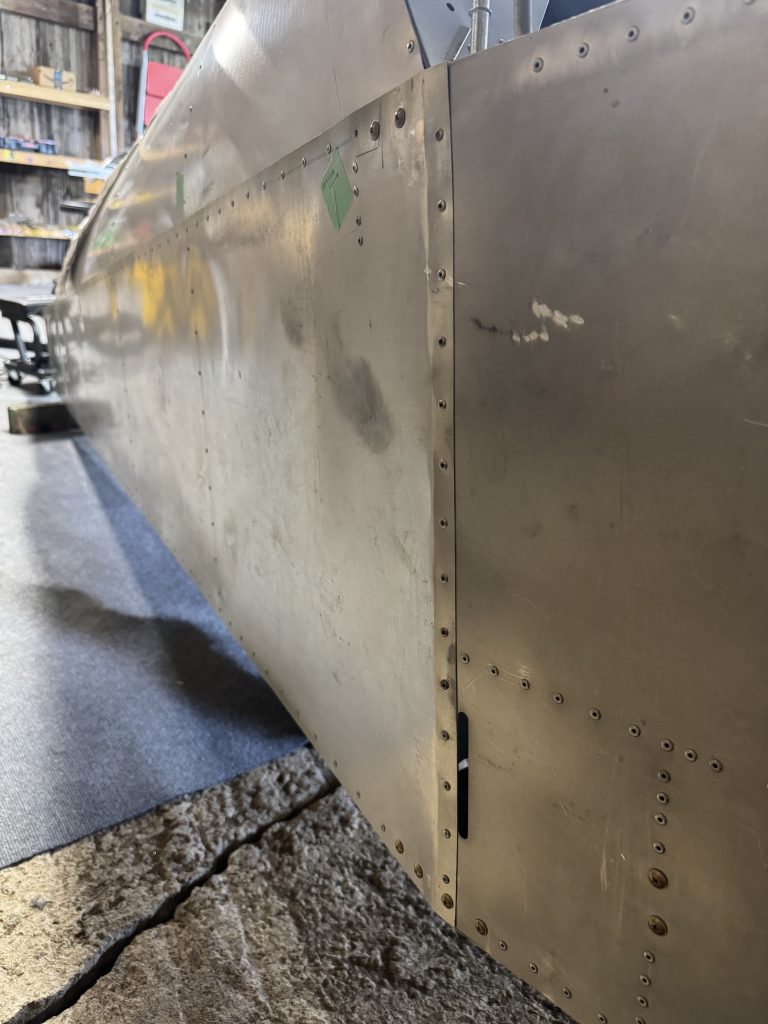
Unfortunately it is not the only error. The cockpit side panels are supposed to be outside of the tailcone side panels. The cockpit side panels are inside of the tailcone side panels, so there is a lip that points into the wind. How or why someone could make this error is beyond me. I will have to separate the cockpit from the tailcone at some point.
This is not such a bad thing. Committing to regressing a little bit in order to ensure a good quality build is a big mental milestone.
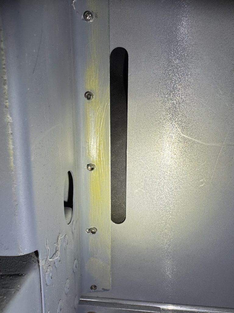
In the cockpit there are also several mis-rivets and many of the rivets were not assembled according to the plans. Here we see the bottom-most rivet has not been set, and it is also too close to the bottom of the component. It will have to be replaced and another rivet added above it. Above that rivet are two more rivets that have been “snowmanned,” or that have been drilled more than once, making a large hole resembling a snowman. Additional rivets will have to be added, as the holding strength of these rivets will not be the same as correctly drilled rivets.
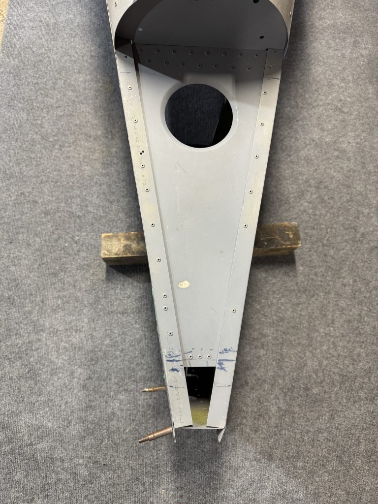
At the rear, these rivets have not been drilled according to the plans at all. They are not even identical left and right. The left should be OK, but I will have to add at least two to the right. Why wasn’t this built according to the plans? It’s not hard, and the plans are excellent.
I still don’t regret buying a kit someone else has worked on, but it sure is hard to find all these obvious errors. How many more will I come across? And, will my tolerance of defects change over time? I will have to be very thorough when going over the rest of the work already done, and carefully analyze the effects of every deviation from the plans.
I will have to build the seat pan, but the kit did not come with any 0.025″ sheet and my local store did not have any. James did give me a full sheet of 0.032″ and recommended building the seat out of that. The difference will be less than 1 pound and it should be a lot more solid.
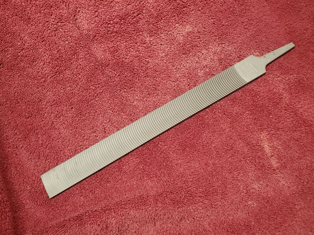
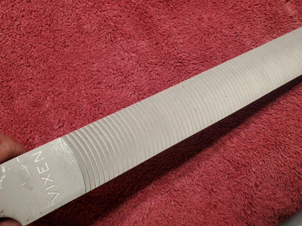
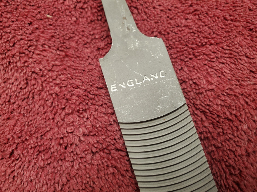
A vixen file is a curved tooth cutting instrument that produces a flat edge by removing lots of metal. The large gaps between teeth and single-direction operation works well for soft metals like aluminum. To make nice flat edges on the control surfaces, I wanted one and could not find one anywhere in Canada. Brown tool has them but I was not ready to place an order from them that justified the shipping cost just yet. Luckily someone on eBay located in Maine was selling new-old-stock vixen files made in England at an attractive price.
I also got these burrs from Amazon for just $56 and they work great; they are solid and not brazed on, they cut straight and fast and the ground shafts are great quality.
I was about to complete the rudder assembly, but ran out of 3/32″ clecos. This assembly will be paused as I wait for them to arrive. Someone on Amazon was selling a cleco kit at just about $1 each! At Spruce they are $2!

-
First look at the wings
While waiting for clecos to arrive I had a look at the wings, starting with the spars. The spar is made up of a .125″ center web with .032″ sheet on either side. One of the sheets is the main spar which is about 12 feet (3.6 m) long and the other sheet is called the aft web. On one side of the sandwich is a 0.090″ doubler. The spar caps go above and below the sandwich.
The story from James is the first builder wanted to put flush rivets through the wing skins into the spar caps. This requires countersinking into the spar caps, which removes some material. Sonex didn’t like that and James bought new spar caps, and had to do some disassembly.
I had 3 main spars, 3 center webs, 2 aft spars, and 2 doublers. I also had some angle hardware including one wing attach block. This had already been drilled to 1/4″ and drilled to fit the spar. However the holes did not line up at all. As I was making up a bunch of angle hardware anyway, I decided to redo it. I also had to make my first order from Spruce for metal and bolts.
Not very straight 🙁 Because there were more components than necessary and some had already been dimpled I had to figure out how to get usable assemblies. Because disassembly had been done there may also have been some destroyed parts.
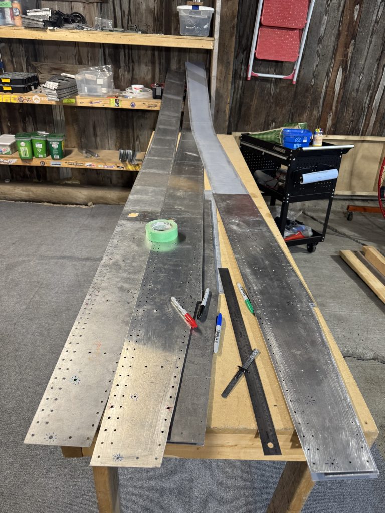
Laying out the wing components. I will need a longer workbench! I think I will be able to salvage this assembly without buying anything, but I am waiting on Sonex for an opinion.
The wing ribs looked mostly OK, except for one outer forward rib that was cut into. There were also some mis-rivets on the root rib and some missing parts. Last, the root rib attach angles were not trimmed up and down. I could do this later during a dry fit, to butt up nicely against the spar caps.

Oops!
Needing more clecos, I made an order from Aircraft Tool Supply who are very well set-up to cater to Canadian customers! I also got some necessary tools like a microstop countersink for WAY less than Spruce sells it for, and some drill bits.
I stopped by St-Lambert airport and met a guy with a Rotax 912-powered ultralight trike and a Rotax 914-powered Kitfox. St-Lambert airport is a private grass strip with very low rent and a good community of ultralight and amateur-built pilots. It’s a little further than St-Jean-Chrysostome, and isn’t maintained in winter, but seems like a great place to meet people.

-
Rudder ready to rivet
With the arrival of a whole whack of 3/32″ clecos I could finish the rudder, and move on to finishing other parts of the tail.
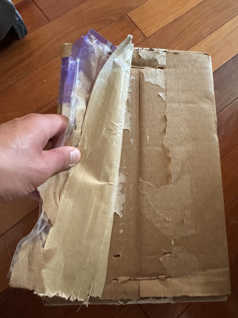
The parcel from ATS is both taped and stapled. Skookum! These guys are serious. 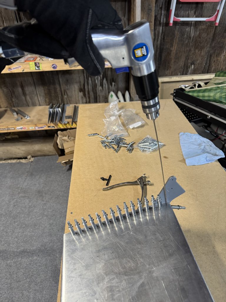
The last two holes here were tricky to drill as the bit was not long enough, so I broke out the new 12″ aircraft extension drill. What a breeze! 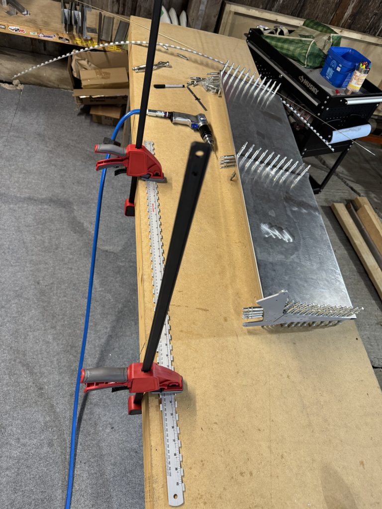
To drill the hinge I used Jeff Shultz’s idea of drilling into a $3 aluminum ruler to get the correct spacing and offset. It worked great! I put down a second hinge so the ruler would rest flat. 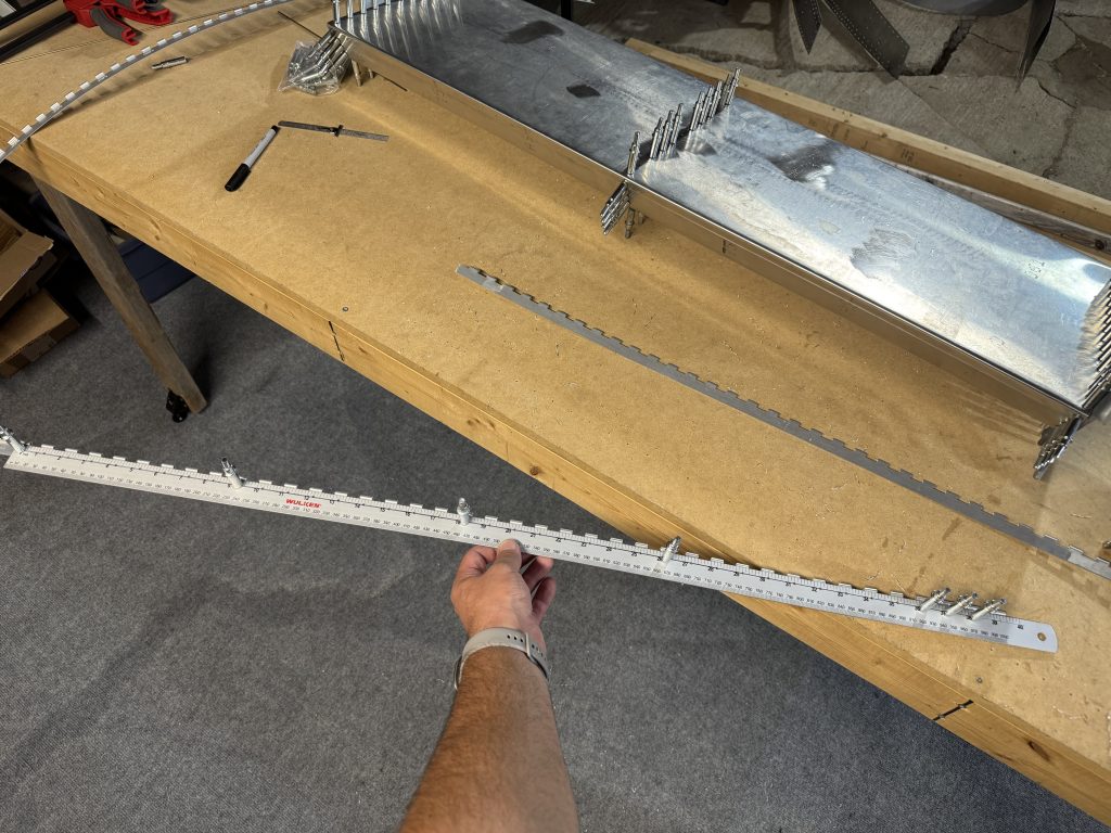
But, I only drilled 39 holes in the ruler, so had to shift the ruler down one hole and cleco it to get the last hole. 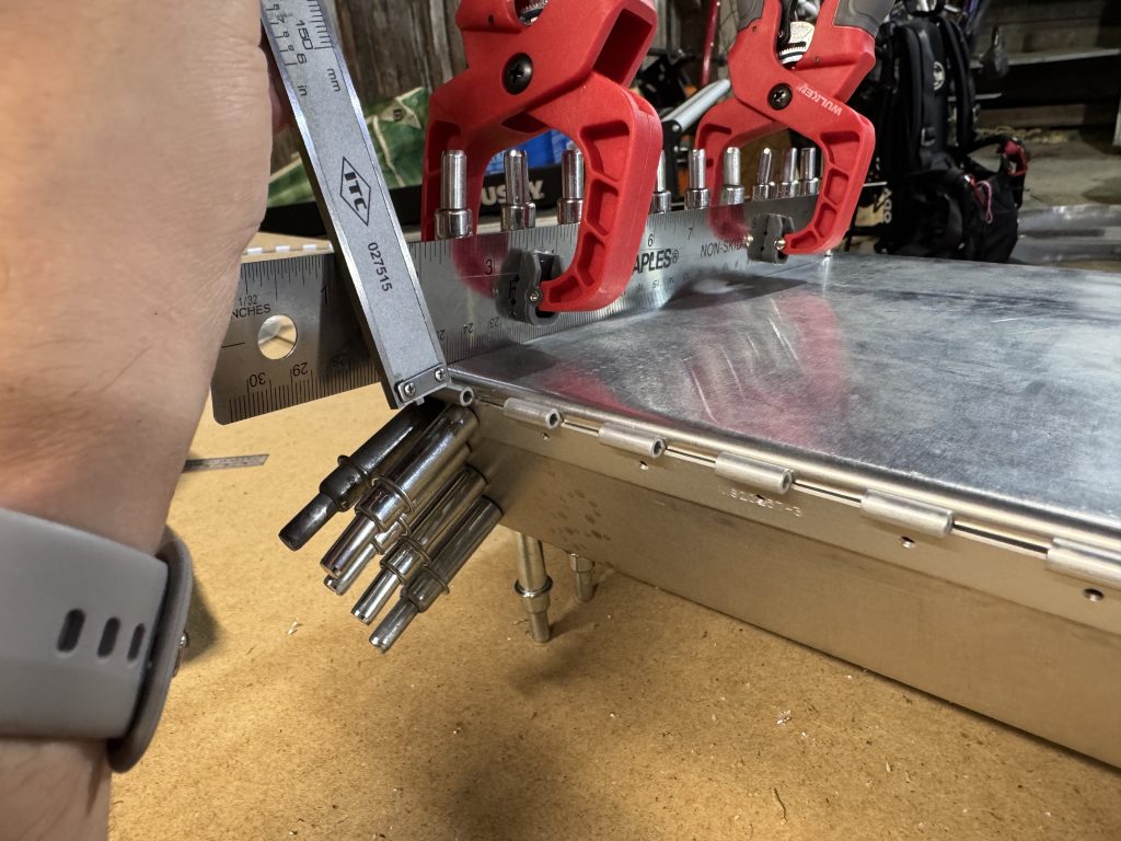
To get the hinge the correct distance from the surface of the rudder, I clamped a straightedge to the clecos and measured down perpendicular to the edge. 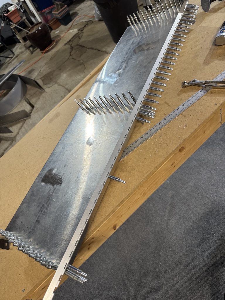
To ensure the hinge was straight, I drilled with the other half of the hinge attached, and flopped it around from time to time to ensure it didn’t bind up. 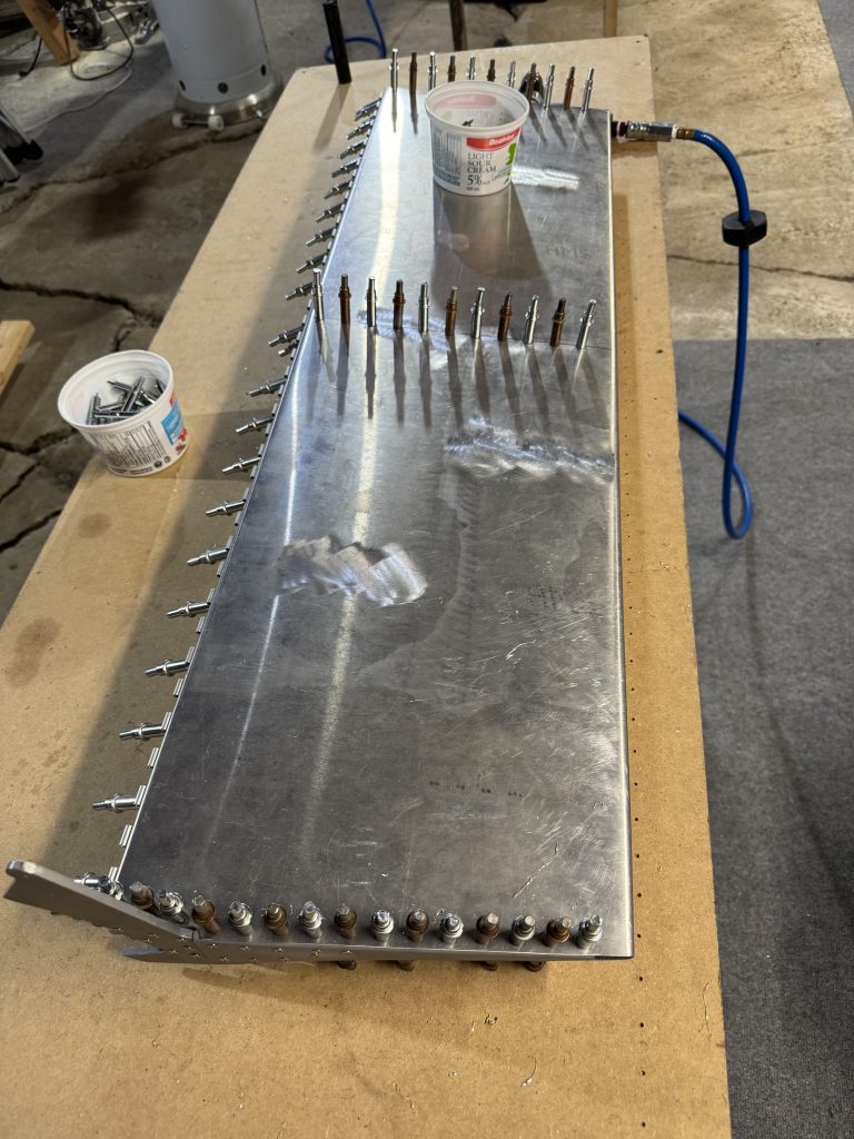
Up-drilling was very fast – now that I have sufficient clecos. 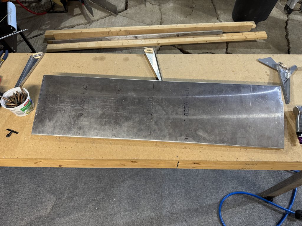
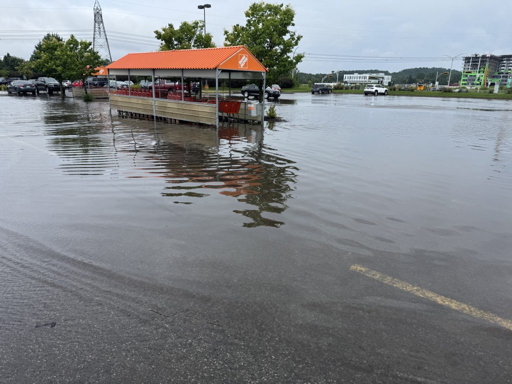
Taken apart again for deburring and final prep. I went to home depot to get some self-etching primer before riveting the rudder, but it was closed due to flooding. It didn’t even rain that much! I will finish the rudder later.
Next, the trim tab.
I made the trim tab in just one night and forgot to take many pictures. It went pretty fast: cut a patch out of a large metal sheet, mark the dimensions on the patch, cut out the profile with snips, perform nice final cuts, mark bends then make the bends, cut and drill the hinge (this hinge also required trimming), drill, updrill, deburr, and rivet, mate the part to the elevator, drill, updrill, deburr, rivet.
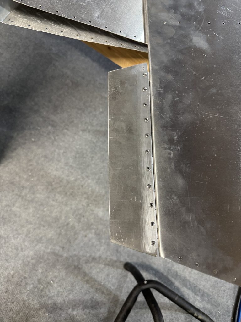
I am not very happy with this part. The edges are not very straight which is just cosmetic but still unsatisfying. The arrival of my vixen file should help in the future. The hinge was too close to the trailing edge of the elevator despite adding a small gap to keep it off, so the hinge binds slightly. Also, the hinge on the elevator side is not perfectly flush with the lower surface of the elevator. It will work, but I will wait until the trim system is installed to see if the binding will be a problem.

The wing spar parts that seemed sketchy will be trashed. Out of 3 main webs none are usable, and one of the doublers will be tossed. The rest is good but I will be placing an order at Sonex sometime after Oshkosh. There are also some wing ribs that were trash and I’ll replace them at the same time. I am not sure if I should order extra parts that I will need some time in the distant future just yet – like the jabiru baffle kit. I think I’ll wait and see. Maybe the exchange rate will get better.